Scope:
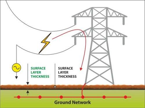
The result of a ground electrode impedance, referenced to remote earth, and the current that flows through that electrode impedance is known as Ground Potential Rise or Earth Potential Rise (as specified in IEEE Standard 367).
The maximum electrical potential that a (substation) grounding grid can achieve relative to a distant grounding point, presumed to be at remote earth potential (as defined by IEEE Standard 80-2000) is known as Ground potential rise or Earth potential rise. The maximum grid current multiplied by the grid resistance equals GPR.
Wherever large electrical currents travel into the earth, the ground potential rise events are a worry, which might happen at a substation, a high-voltage pole or tower, or a transformer. Grounding precautions are essential where an Earth Potential Rise event is a concern regarding the safety of workers and equipment. The earth’s electrical potentials drop sharply around the perimeter of a grounding system, but not to zero. In reality, when one has reached a distance that is a small number of grounding, soil potentials are inversely proportional to the distance from the centre of the grounding system. This happens in homogeneous soil.
What is Ground Potential Rise (GPR)?
The primary goal of a Ground Potential Rise Study is to determine the amount of hazard for personnel or equipment at a specific high-voltage location. Once done, certain steps can ensure that the place is safe.
The engineer must determine the minimum grounding system required for each location and consider all municipal and federal criteria, utility company and other restrictions imposed.
Ground Potential Rise (GPR) Study is to identify how electrical faults, lightning strikes, or short circuits will affect personnel and equipment in the fault zone. Understanding what the clearing time and dissipation of the high-voltage event will be in the event of a ground fault provides the safest and most cost-effective grounding system design.
Criteria to study Ground Potential Rise (GPR)
-The square footage, size and layout of the proposed grounding grid
-Resistance-to-ground of the proposed grounding system
-The estimated fault current that would flow into the grounding system
-Ground Potential Rise (in volts) at the site, 300 Volt Peak lines, the X/R Ratio, and the fault clearing time in seconds
These are typical items reported in a Ground Potential Rise Study. The indicators of safety, step and contact potential voltages.
To successfully conduct a Ground Potential Rise Study, the grounding engineer requires three criteria:
1) Test data of soil resistivity
2) Drawings of the proposed development of the test site
3) Electrical utility data for testing and validation
Test of soil resistivity:
If possible, the apparent resistivity readings at pin spacings should be ranging from 0.5 to 1 ft to a maximum of three grounding grids (diagonals should be included). The source of concern for worker safety is touch and step voltages. For building a cost-effective and safe grounding system, it is necessary to understand the characteristics of the soil at depths. They should be ranging from immediately underfoot to one or more grid dimensions.
Drawing of proposed test site:
The plans should include the configuration of the high-voltage tower or substation, including any new equipment development that may be taking place on the site (like fencing, gate radius, incoming electricity and telecommunications lines). During the survey, document the height and spacing of the conductors carried on the tower and any overhead ground wires in the case of high-voltage towers. This data is required to effectively resolve any touch or step voltage issues that may arise on the job site.
Electrical Utility Data:
The electric utility company must provide the data on the tower or substation under consideration. The name of the substation or tower number, the voltage level, the sub transient X/R ratio, and the clearing times should all be a part of this information.
In the case of towers, the line names of the substations involved. The amount of current contributed by each substation in the event of a problem. The kind and position of the overhead ground wires concerning the phase conductors put on each tower/pole.
Tower or pole ground resistances along the line (measured or average values) are required if overhead ground wires are present.
Important aspects required from the electrical utility:
Each power line circuit contributes a certain amount of phase-to-ground fault current
Time for fault repair
The voltage on the transmission line
X/R ratio value of sub transient condition
Continuity and bonding configuration of the ground wire
Tower-to-tower and tower-to-substation distances on average
Ground resistance of typical tower/poles: measured or calculated
Hazardous Voltages due to Ground Potential Event:
Fibrillation Current is a figure based on statistics representing the amount of electricity required to trigger cardiac arrest in a person. IEEE Std 80-2000 lays out a method for determining the relevant value of Fibrillation Current for a safety investigation, as well as a thorough description of calculation.
There are other techniques for determining Fibrillation Current; however, in North America, the 50kg IEEE method is the most widely used. The Fibrillation current level is inversely proportional to the square root of the fault duration. However, adding a correction factor depending on the sub transient X/R ratio is mandatory.
Personnel Safety During Potential Rise Events on the Ground:
Grounding engineers’ safety system protects workers operating in areas where GPR hazards are known. For the safety of workers, federal law requires that any known danger must be removed from the workplace. For complying with the law, the engineer might choose voluntary standards. Step and Touch Potentials must be eliminated on transmission and distribution lines that include any linked communication equipment, according to federal legislation 29 CFR 1910.269.
They must be excluded from substations because they are always considered workplaces. Transmission and distribution towers/ poles are not working locations and are frequently exempt from these regulations. The tower on a mountain or in the middle of the desert is not always a workplace. Any high-voltage tower or pole, on the other hand, becomes a workplace as soon as non-electric utility company equipment is installed and requires outside vendors to support the new equipment.
Interesting facts of Ground Potential Rise (GPR) in power system applications:
– Regardless of tower footing resistance, a peak GPR will develop at a faulted tower.
– A peak GPR value corresponding to a different tower footing resistance could be drastically different. A faulty tower with higher resistance will have a higher peak GPR.
– A tower fault is more severe than a local substation. It not only causes a peak GPR but also causes voltage potential to rise at both local and remote substations.
– If a fault occurs at a local substation, the GPR at both substations is similar. But if a problem occurs at a tower adjacent to the local substation, the GPR at the local substation is substantially higher than that at the remote substation.
– At the faulted tower, peak fault currents at shield wires will occur.
– Footing fault currents have a big spike at the local substation, representing the total fault current returns to the station grounding grid, which is the sum of currents from shield wires and ground.
– The peak fault current for a given tower footing resistance is always found at the local substation, with some footing fault current passing through the faulted tower but at a much lower value.
– GPR and fault currents are affected only slightly by fault types and faulted phase.
– The GPR at the faulted tower is more when the average span is longer.
– When adopting a different average span, the effect on GPR and fault currents at shield wires are obvious, while the influence on the footing fault current appears to be small.
Impact of GPR on Telecommunication System:
Protection of Telecommunication System:
During a power system fault, copper wire communications cables in high voltage situations (substations, power plants, transmission towers) can be exposed to thousands of volts. The entire site will undergo a ground potential spike at that point, and dangerous potential discrepancies can emerge. It can happen between the power station and the telecommunication cable’s remote (theoretically “zero”) ground.
Any voltage difference will cause a current flow, which might harm a person or sensitive electronics as the potentials equalise.
Various Zones of Voltages:
Unprotected copper wires are outside the 212-volt RMS (or 300-volt peak) zone. They are out to protect the telecommunications infrastructure. Inside that zone, wires must be secured under IEEE Standards 487 and 1590. Three voltage levels have been identified in IEEE Std. 487:
Level I: Peak voltage of 300 volts.
Level II: Peak voltage of 301 to 1,000 volts.
Level III: Peak voltage of more than 1,000 volts.
The placement of the Copper-Fiber Junction is the focus of IEEE Std 1590 (CFJ). It must be outside the 300-Volt peak zone or a minimum of 150 metres away from the station, whichever is less.
Read more about Earthing & Lightning Protection in our blog section
Click here to view all of Axis’s Lightning Protection, Lightning Arresters and Earthing products.
Thank you for reading the blog, Axis is a leading manufacturer and supplier of Electrical Components to over 80+ Countries. Talk to our industry expert by visiting our contact us section. You can also watch our videos by our experts – click here.
Follow us on LinkedIn for regular updates on our Products!


