


The protection radius of an ASLA is related to its height (h) relative to the surface to be protected, to its efficiency, and to the selected protection level.

for ≥ 5m
for 2m ≤ h ≤ 5m
where,
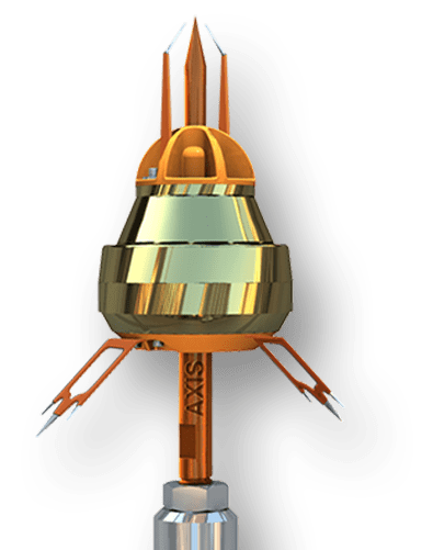
How to Install an Early Streamer Emission (ESE) Lightning Arrester
Proper installation of an ESE Lightning Arrester ensures optimal protection and compliance with IEC standards. Follow these steps for safe and efficient installation:
1.Choose the Correct Location:
Mount the ESE Air Terminal at the highest point of the structure to ensure maximum coverage and an unobstructed path for upward streamers. The arrester should extend above all nearby structures or metallic components.
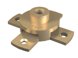
2.Install the Mounting Mast:
Securely fix the supporting mast using corrosion-resistant brackets or clamps. The mast must be mechanically strong and properly grounded. Ensure that the mast height and position meet the radius of protection defined in IEC 62305 and NFC 17-102 standards.
3.Mount the ESE Air Terminal:
Attach the ESE lightning arrester to the top of the mast. Tighten all fasteners securely to withstand high wind speeds and vibrations. The arrester should be vertically aligned for accurate streamer emission.
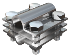
4.Connect the Down Conductor:
Use a certified copper or aluminum down conductor to create a direct, low-resistance path to the ground. Connect it firmly to the base of the arrester using appropriate clamps. Avoid sharp bends (minimum bending radius: 20 cm) to prevent impedance build-up.
5.Grounding System Connection:
Connect the down conductor to an effective earthing system, maintaining an earth resistance below 10 ohms. The grounding system may include chemical earthing electrodes or copper-bonded rods as per site conditions.
6.Install the Lightning Strike Counter (Optional):
To monitor lightning activity, install an analog or digital lightning strike counter along the down conductor at an accessible height. Ensure proper alignment and weatherproof sealing.
7. Inspection and Testing:
After installation, check all electrical and mechanical connections. Conduct an earth resistance test and verify the continuity of the down conductor. Annual inspection is recommended to maintain performance and compliance.