Follow us on LinkedIn for the latest updates
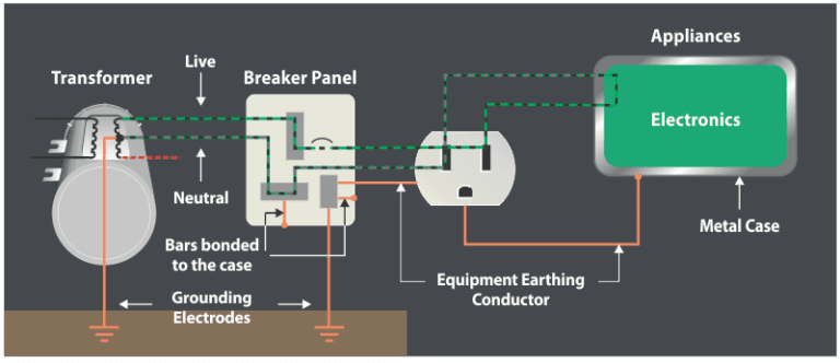
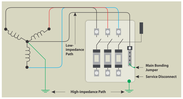
The importance of Bonding, Grounding and Earthing in electrical systems cannot be overstated. In a factory, in order for the equipment to function properly, the grounded circuits need an effective return path from the equipment to the power source. In any kind of construction, the non-current carrying metallic parts in that facility need to be connected together to avoid a voltage potential between them – these metallic parts can include the steel rebar, metallic enclosures and even the piping running alongside the building. While Bonding, Grounding and Earthing are used interchangeably, there are actually differences between the technical definition of all three of them. The figure shown below is an example of the differences between Bonding, Grounding and Earthing.
Introduction to Grounding or Earthing
A conductor in an electrical wiring system that offers a low impedance path to the earth is known as the earth or the ground. The purpose of this earth or ground is the prevention of dangerous voltages. While Grounding is a more commonly used term in North America and its standards (IEEE, UL, ANSI, NEC), Earthing is the more commonly used term for the UK, Europe and most other parts of the world (IEC) including India (IS). For example, Earth Rods and Ground Rods (click to learn more about Earth Rods) are used for the same product but in different geographies.
Equipotential Bonding
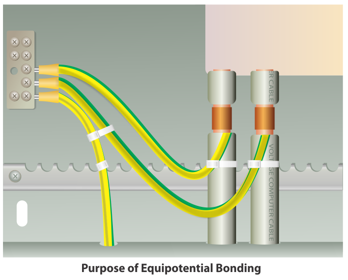
Simply put, joining two electrical conductors is bonding. The act of connecting two electrical or metallic object to form equipotential between them is called Bonding. Current flows in two conditions: firstly, to close a path and secondly due to potential difference between two points. Therefore, by forming equipotential between two metallic objects, we are preventing current flow between them. Equipotential Bonding is always done on metallic parts which do not have any potential or which are not designed to carry any current.
The main purpose of Equipotential Bonding is personal safety of someone who may accidentally touch a metallic object and to protect the equipment. When a fault occurs, possibly due to a lightning strike, a large amount of current flows to the ground. If any metallic part or metallic structure is not connected to the earthing system, a potential difference will be generated which can create sparks that can cause a fire or harm nearby humans or equipment.
If a person touches equipment which are not electrically bonded, then they are at risk of receiving an electrical shock due to the difference in the potential.
Earthing
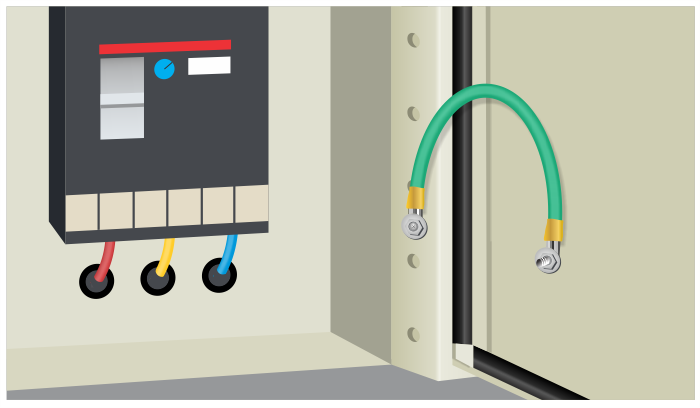
Earthing refers to connecting equipment or metallic parts which do not carry current under normal conditions to the earth using Earth Electrodes. This could include the frames of electrical equipment frames, enclosures, supports etc. and in this case, the term used would be body earthing. Rebar clamps can be used to Earth the rebar structure of a building as well.
At the time of a fault, very high levels of current will flow through the system. As a result, a potential difference is produced between the external metallic parts of the system and the ground. Due to this change in the potential, if a person comes in the contact with the system the current would flow through them instead and cause an electric shock. Thus, non-current carrying metallic parts are connected to the earth to so that these kinds of fault currents can flow safely to the ground.
Grounding
Grounding refers to connecting the current carrying parts to the earth. For example, in the case of a distribution transformer system whose neutral point is generally known as the star point, it is directly or indirectly connected to earth to protect the transformer & distribution system in case of abnormal conditions in the electric circuits.
In a case where the system neutral is connected to earth without any resistance or impedance, this system is known as a Solidly Grounded System and if the system neutral is connected to earth through a resistance, this system is known as a Resistance Grounded System.
As per IE rules/CEA safety requirements, 415 V systems in India should be solidly grounded systems and as per DGMS safety requirements, 415 V systems in Oil fields/plants and Mines in India should be resistance grounded. Systems above 415 V may be resistance grounded as per application requirements in industrial plants.
You can view our wide range of Earthing, Grounding and Bonding Equipment here. You can contact us if you want a quotation or have any further questions regarding products required for Earthing, Grounding or Bonding.
This article is part of our series of articles on Lightning Protection, Surge Protection & Earthing, you can read more with the following links:
Surge Protection Devices (SPD)
Lightning Protection Zones and their Application to SPD Selection
How does a Lightning Arrester work?
For more information, please contact us at axis-india.com/contact-us/