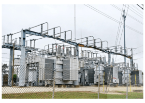
Earthing is an important part of electrical distribution lines. Installation of a protective grounding on the power line structure creates a safe work zone. It neutralises leakages or short-circuit current and offers a simple and easy path for the current to the earth with zero damage potential.
Importance of Earthing
In electrical installations, earthing or grounding transfers an immediate discharge of the electrical energy (faulty current) to the earth. It is an electrical circuit that connects parts of the electrical system to the ground, providing an easy path (a protective conductor or electrical connections).
Properly implemented earthing systems help protect a structure in several ways:
1. Personnel working with the electrical lines are protected from being hit or injured due to short-circuits current. The faulty current gets neutralised as it flows easily through the earth wire even if there is fault insulation or leakage.
2. Ensures undisrupted power supply despite short-circuits or lightning strikes and protects personnel who perform routine tasks.
3. Electrical lines, poles, apparatus, and personnel are protected from high voltage surges during a lightning discharge.
Role of Earth or Ground Wire
Ground wires or earth wires offer a shield to the line. Earth wires intercept lightning strikes before they can hit the conductors or power lines, protecting them from damage and power surges. These earth wires are bare conductors placed and attached at the top of the transmission towers.
Generally made of steel, ground wires do not carry any current and are firmly connected to the ground at each tower in the transmission and distribution system.
Separate methods are followed for lightning protection and earthing of distribution lines as described in the following sections.
Earthing or Grounding of Distribution Lines
Electrical Earthing is done by connecting the non-current carrying part of the equipment or neutral of the supply system to the ground. For distribution lines, wire earthing is used by low resistance wire known as the earth wire. This earth wire is connected to Earth Electrodes, buried in the ground. For this, horizontal trenches are dug, and strip electrodes get buried inside these trenches. The electrodes are of copper, galvanized iron, or steel. Sometimes, round conductors are also used on the ground.
Earthing for Lightning Protection
The earth wire in overhead transmission lines has voltages of 110kV and above. For lightning protection:
– Earthing is integrated with a lightning protection system and low current systems. Modern power systems add two ground wires for more protection. Compared to a single wire, these do not affect switching surges, and the coupling effect is higher with low surges.
– The resistance between the earth and tower base is kept low. Waves are produced when lightning strikes the ground wire. They travel along the line in the opposite direction and reach the adjoining tower which passes them safely to the earth.
– The ground wire also protects the power line conductors from direct lightning strokes. In HV transmission lines, lightning may cause a towering rise of voltage before reaching the ground wire. It may cause flashovers. To minimize this and control the degree of flash-overs proper grounding and Earthing of the poles are implemented by deep Earthing rods or counterpoise wires.

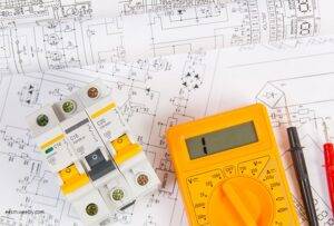
Processes & Standards
As there are two non-current-carrying parts in an electrical system: the neutral of the system and the frame of the electrical equipment. Earthing too has two classifications:
1. Neutral Earthing or System Earthing: Mostly provided to systems with star winding (generator, transformer, motor, etc.) Here the neutral of the system is directly connected to the earth by a GI wire.
2. Equipment Earthing: These are provided to the electrical equipment’s non-current carrying parts. Their metallic frame is connected to the earth with the help of the conducting wire. In case of a fault in the apparatus, short-circuit current passes to the earth through this wire.
The Earthing standards used across the world are:
1. IEC 60364-1 and 60364-4-41 Electrical Installations in Buildings.
2. BS 7671 Requirements for Electrical Installations (lEE Wiring Regulations).
The wiring regulations of BS7671 describes the earth conductor and protective bonding conductor. It lists five types of Earthing Systems: TN-S, TN-C, TT, TN-C, and IT.[3]
T= Earth
N = Neutral
S = Separate
C = Combined
I = Isolated
The calculation process of the Earthing conductor and main protective bonding conductor sizes (copper equivalent) for TN-S and TN-C-S supplies are:
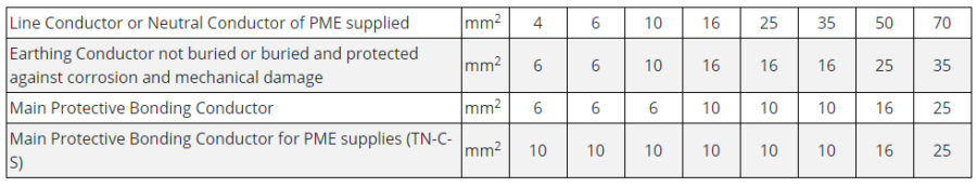
Various Earthing Systems follow the guidelines mandated by these standards.
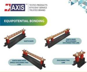
Installation
An Earthing system is the combination (contacting assembly) of the Earthing and its connection. Earthing parts are electrically connected to some system of electrical conductors or electrodes placed near the soil or below the ground level of installations. The grounding, Earthing mats, or electrodes create an electrical connection between the parts and under the ground level. These have a flat iron riser that connects all the non-current-carrying metallic parts of the equipment.
During a fault:
1. The faulty current flows through the Earthing system to the earth from the Equipment Earthing terminal to the ground.
2. The earth mat conductors’ voltage rises and becomes equal to the resistance of the earth mat multiplied by a ground fault.
Grounding for Transmission and Distribution Lines
Single-phase grounding of multi-phase circuits is avoided. All conductive objects within the workers’ reach (aerial or on-ground) are bonded to the grounding system. Their placement ensures adequate protection to the worksite.
– The earth is never used as a protective grounding conductor; neither should it be used as part of a circuit path between protective grounds.
– Overhead ground wires are bonded to the worksite grounding system (structural steel) with protective grounds for workers who will work nearby. Bonding of overhead ground wires to the worksite structure reduces step-and-touch exposure voltages on the ground. They divert fault currents away from the structure footings to adjacent structures in case of accidents.
Grounding and Earthing of Transmission Structures
Wood Pole
Three-phase grounding application on structures using grounding cluster bars is preferable. These bars are:
Placed just below the lowest elevation of the lineman’s feet at the work zone (approximately at the same elevation as the phase conductors.)
They are bonded to the pole structure ground leads (if provided.) The bar provides a convenient point of attachment for protective grounds and a bond to the pole structure ground wire.
Protective grounding jumper installation is for two-pole and three-pole (grounded) structures. Before the installation of permanent grounding, the pole footings are examined for damage, omission, or poor continuity between the structural hardware and pole ground electrodes. If there is a defect, a temporary ground rod is installed next to the pole and attached to the worksite grounding system.
Distribution Poles
Earthing with Galvanized Iron is used. Copper wires are used for Earthing-lead or joint. For high installations, copper strips are preferred as they can carry higher values of fault current due to their width.
Grounding cluster bars are used for the protective grounding of distribution lines and aerial cable terminations. They are placed just below the lowest elevation of the lineman’s feet for the work zone and bonded to the neutral conductor and pole ground lead (if provided).
The position of the cluster bar defines the lower boundary of the work zone on the pole. Alternatively, the connection of individual protective grounds from the cluster bar may be built to each phase conductor. This may produce marginally higher exposure voltage.
Only damage-free pole ground wires are to be used for protective grounding. In absence of pole grounds, a temporary ground rod can be inserted or screwed into the earth next to the pole and attached to the cluster bar with a protective ground.
Conclusion
Earthing of distribution line structures creates a safe work zone on the structure. The ground mats, hazardous step, touch, and transferred touch potentials may still exist on the ground. It may present near the footings and objects bonded to the worksite grounding system if there is any accidental energization of the line. Therefore, you should buy only tested products.
Here we have tried covering the steps in planning for Earthing for a Distribution or Transmission Line. To know more about our products, click here or feel free to email us.

This article is part of our series of articles on Lightning Arresters, Surge Protection & Earthing, you can read more with the following links:
Surge Protection Devices (SPD)
Lightning Protection Zones and their Application to SPD Selection
How does a Lightning Arrester work?
Follow us on LinkedIn for regular updates on our Earthing and Lightning Protection Products!