Objective:
Indian Standard IS: 3043 – 2018 [Code of Practice for Earthing – Second Revision] says the following: Earthing refers to the complications which arise when electricity conducts via the ground. The terms earth and earthing here are used whether (or not) the earth is employed as a low impedance fault current return path. Earth is now employed for regulating the voltage of system neutrals rather than as part of the return circuit. The earth connection ensures service continuity and protects equipment and human life from damage. This article states different opinions & analyses related to neutral grounding in electrical systems.
Earthing Object:
IS:3043 further states that the purpose of an earthing (grounding) system is to provide a uniform potential and as close to zero or absolute earth potential under and around a station. So that all parts of apparatus other than lives are at earth potential. Including operators and attendants.
Providing such an earth surface of uniform potential under and surrounding the station, there can exist no difference in a short distance (big enough to shock or injure an attendant when short circuits occur). The Code suggestions are to realise these goals.
System Earthing Vs Equipment Earthing:
Earthing associated with a current-carrying conductor is essential to the system’s security and is known as system earthing. Earthing of non-current carrying metalwork and conductor is known as equipment earthing. Necessary for the safety of human life, animals, and property.
What is Grounding in an electrical system?
It refers to both equipment grounding and system grounding. The connection of non-current carrying conductive objects such as conduit, cable trays, enclosures, and motor frames to earth ground is called equipment grounding. System grounding in electrical refers to the solid or current-limiting connection of the neutral points of current-carrying conductors, such as the neutral point of a circuit, a transformer, spinning machinery, or a system, to earth/ground.

What is an Ungrounded System?
The systems were little back then, and they were not interconnected to form a grid. The most conspicuous fault was an earth-fault, due to its modest size was frequently self-extinguished. The reason is the idea of being ungrounded neutral and not jeopardising service continuity.
As the size of electrical systems developed in terms of enormous transmission line networks, steady-state and transient overvoltage began to occur on the transmission lines. The voltage of the phases that were not affected by the problem increased by 1.73 times. This resulted in setting a strain on the insulation, eventually causing it to fail. In the delta system, a line to ground voltage surged over 2.5 times the typical voltage when neutral instability has occurred.
In a healthy system, the neutral voltage to the ground is zero. When a ground fault occurs, the neutral voltage rises in proportion to the fault’s severity. As a result, the neutral becomes unstable as its voltage varies concerning the ground.
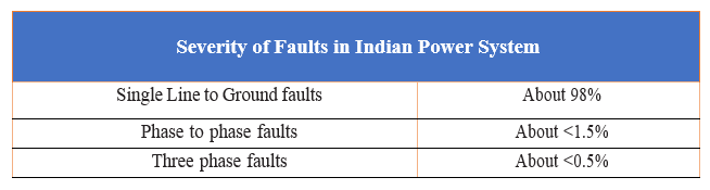
Natural disturbances such as lightning, high-speed winds, earthquakes, and other factors such as trees falling on overhead lines or support structures generate power system faults. Faults in an industrial power system can occur in the following range.
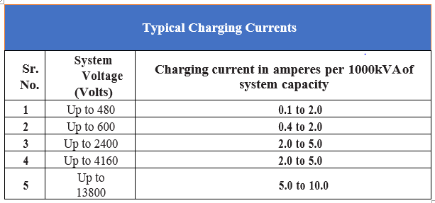
Charging currents in LV systems range from 0.1 to 2A, up to 10A in 13.8kV systems. A typical range in the table below:
Multiple Ground Faults:
On ungrounded neutral systems, this can happen. While a ground fault on one phase of an ungrounded system does not produce an outage. It’s because the fault-free phases have line-to-line voltage impressed on their line-to-ground insulation. The longer the first ground fault lingers, the more likely a second ground fault will occur on another.
Insulation has overstressed by up to 73%. In addition, the system is degrading at a faster pace due to the cumulative overvoltages imposed by successive ground faults over several years.
Classification of Various Grounding in Electrical Systems:
Solidly Grounded – When the neutral of every generator or transformer bank in that area is connected solidly and permanently to the earth through a solidly grounded connection, the station is adequately grounded. When all the system’s critical producing or transmission stations are adequately grounded, the system is deemed well-grounded.
Resistance Grounded – When every generator’s neutral or transformer bank in that section is connected (permanently) to the earth through a low resistance connection, the station is resistance grounded. When all of a system’s main generating stations or transmission stations connect by a low-resistance connection, its resistance is grounded.
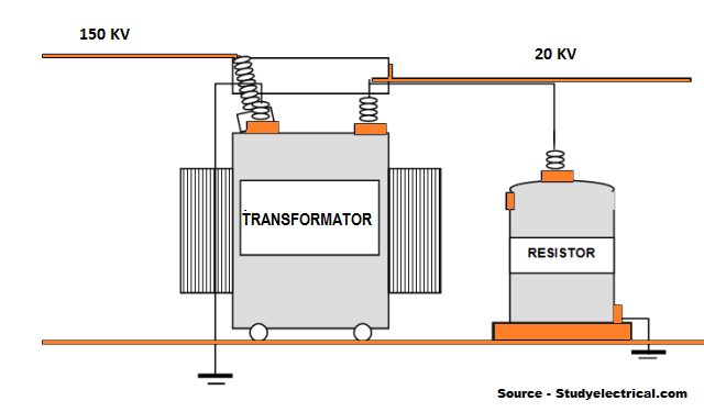
Reactance Grounded – When an air- or iron-core reactor is between neutral and the earth, the system is deemed reactance grounded. This is true whether it’s via a grounding transformer or a portion of the generator or transformer capacity is reactance grounded at any given moment.
Ungrounded – A system is ungrounded if there are no conductive paths between the neutral and the earth other than a potential transformer. There are chances of a heavy short circuit or dead short circuit for such an arrangement if proper grounding is absent.
Concept of Effective Grounding:
The degree of system grounding stated in IEEE142 determines the effectiveness of a solidly grounded system. The following are the two most important requirements:
1.- The line to ground fault ILG at least 60% of the permissible three-phase fault current I3ϕ
2.- The second criterion is that the un-faulted phase voltage to ground (VUNF) must be at least 80% of the systems rated line to voltage (VLL).
Summary:
This blog has documented some fascinating historical opinions and the slow but steady growth of the foundation concepts up to today’s practice (and standards). Resistance grounding, reactance grounding, and tuned reactor grounding in electrical systems are in addition to successful grounding analyses.
![]()
Read more about Earthing & Lightning Protection –
Surge Protection Devices (SPD)
Lightning Protection Zones and their Application to SPD Selection
How does a Lightning Arrester work?
Click here to view all of Axis’s Lightning Protection, Lightning Arresters and Earthing products.
Thank you for reading the blog, Axis is a leading manufacturer and supplier of Electrical Components to over 80+ Countries. Talk to our industry expert by visiting our contact us section. You can also watch our videos by our experts – click here.
Follow us on LinkedIn for regular updates on our Products!