In this blog, we’re focusing on the essential differences between Galvanised Iron Pipe Earthing, also known as GI Earthing, and Copper Plate Earthing. By the end of this blog post, you will get a clear picture of:
- The Objective of Earthing
- Various Methods of Earthing
- Major Differences between GI Pipe and Copper Plate Earthing
The objective of Earthing
1) Safety for Humans
First and foremost, earthing helps protect people from electrical shocks. When a fault occurs in an electrical system, earthing diverts the dangerous current away, sending it into the ground. This process acts as a backup safety route for electrical faults, making it a life saver.
2) Protection for Structures and Equipment
Earthing also provides a shield against sudden increases in voltage, which could be due to events like lightning strikes, power surges, or accidental contact with high-voltage lines. It channels these excess voltages safely into the ground, preventing damage to electrical systems and structures.
3) Voltage Stabilization
Lastly, earthing helps stabilize voltage levels across your electrical network. Since electricity comes from multiple sources each with its own transformer, managing these different voltage levels can be challenging. Earthing uses the Earth as a universal standard, simplifying the management and balancing of voltages from different electrical sources.
Click here to have a look at our UL Listed Earthing Materials.
Methods of Earthing
Iron/Copper Plate Earthing:
Cast iron plates measuring 600 mm x 600 mm x 12 mm for plate style earthing OR a 600 mm × 600 mm x 6 mm galvanised iron plate OR a copper plate with dimensions of 600 mm x 600 mm x 3.15 mm.
The plate is buried vertically at a depth of 8 feet, and a GI strip of 50 mm x 6 mm bolted to the plate is pulled up to ground level.
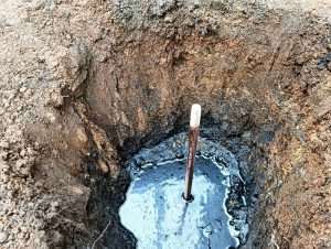
Up to 4 feet from the bottom of the pit, these earth pits are usually filled with an alternate layer of charcoal and salt.
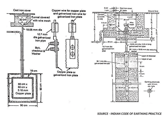
Pipe Earthing:
GI pipe [C-class] of 75 mm diameter, 10 feet long, welded with 75 mm diameter, GI flange with six holes for the connection of earth wires, and insertion in the ground by auger method is the standard practice for pipe type earthing.
These earth pits are filled using an alternate layer of charcoal and salt or an earth reactivation mix.
Galvanized Iron (GI) pipe is an earth electrode for earthing house wiring, factory wiring (especially electrical installations in large industries), neutral wire of the supply line, and other applications.
The pipe’s size is determined by the fault current and the soil’s condition. If moist and soft soil is present in the earth pit, the pipe should be at least 2 metres long with a diameter of 38.1 mm, according to the Indian Code of Practice.
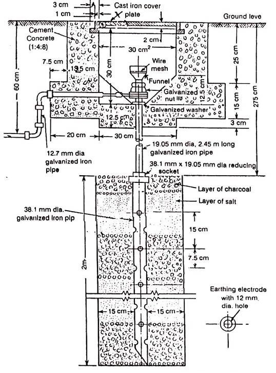
Source - Indian code of earthing practice
The length of the pipe should be increased to 2.75 metres if the soil is dry and rocky. In such cases, 12mm diameter holes are drilled into the pipe at equal intervals with its length for excellent contact between the inner surface of the pipe and the earth.
Galvanized iron wire or strip is used as an earth lead, while the pipe is an earth electrode. The maximum current that will flow through the earth wire when a fault occurs will determine the size of the earth wire. The cross-section of this wire, on average, is 0.645 square centimetres.
Talk to our engineers!
Copper Plate Earthing:
According to Indian Standard, if a galvanised iron plate is used as an earth electrode, its dimension must not be less than 60 cm × 60 cm x 6.35 mm (2 ft x 2 ft x 12 in). As an earth lead, galvanised iron wire is with this plate.
In the case of a copper plate earthing, the plate must be at least 60 cm × 60 cm x 3.18 mm (2 ft x 2 ft x 18 in) in size, with copper wire serving as the earth lead. The plate is inserted vertically in the earth hole at a depth of at least 3 metres (10 feet), below ground level in both circumstances.
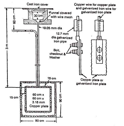
Source - Indian code of earthing practice
Soil’s condition determines the depth of the plate in the earth pit. It must be placed in a constantly damp environment. The earthing becomes a source of risk if the soil surrounding the plate gets dry and hard. As a result, it is vital to test the earthing system regularly.
Importance of Earth Resistance in GI and Copper Earthing
When an earth electrode system is developed, the earth resistance between the electrode and the “Real Earth” must generally be measured and confirmed. The 3-point measuring technique is the most frequently used method of determining an earth electrode’s earth resistance.
The earth tester terminals C1 and P1 are shorted and connected to the earth electrode (pipe).
The two separate spikes inserted into the earth are connected to terminals P2 and C2. Because these two spikes are in the same line at 25 and 50 metres, there will be no reciprocal interference in the field of these terminals.
We receive direct earth resistance on a scale if we rotate the generator handle at a specified speed.
The length of a spike in the earth should not exceed 1/20th of the distance between two spikes.
Increase or decrease the distance between the tester electrode and the spikes by 5 metres to verify resistance.
Wire lengths should typically be between 10 and 15 metres or 62 per cent of the ‘D’ value.
If the distance between the Earth Electrode and the Current Spike is D = 60 ft, the distance between the Potential Spike and the Earth Electrode is 62 per cent of D = 0.62D, or 0.62 x 60 ft = 37 ft.
The calculation for GI Earthing VS Copper Plate Earthing
1) As per IS 3043 for earthing: Plate electrode to ground resistance (R) = (r/A) X under root(P/A).
2) Where r = Soil Ohm-meter Resistivity, A=m3 Earthing Plate Area.
3) Pipe electrode to ground resistance (R) = (100r/2L) X loge (4L/d).
4) Where L is the pipe/length rod’s in cm and d is the pipe/diameter rod’s in cm.
5) Rod resistance to the earth is influenced by the soil resistivity and the physical parameters of the electrode.
6) In terms of earth resistivity, material resistivity does not play a significant effect. Any substance of a particular size would provide the same resistance to the earth. Except for the earthing conductor’s size, number and the protecting conductor’s size and number.
Significant aspects for Copper VS GI Plate Earthing
Copper earthing refers to the usage of copper, which is a superior electrode due to its high conductivity.
In the earth pit, the copper pipes are inserted to maintain resistivity in soil or rock environments.
To complete the earthing system, G.I earthing uses mild steel pipes with a galvanised iron coating. Steel is also an excellent conductor of electricity, allowing any potentially dangerous voltage to flow to the ground and away from you.
Copper has a longer life than GI, and empirically, it lasts 8-10% longer. As a result, the earth electrode of GI material is overdesigned by 8 to 10%.
When sizing the earthing conductor that connects the equipment to the earth electrode, the conductor’s short-term withstanding capability differs depending on the conductor’s construction material.
How to Reduce the Earth Resistance?
a) Joint oxidation should be removed and reduced (for corrosion effect)
b) Avoid any loose connection by strengthening joints
c) Earth electrodes should be large in size
d) The electrodes should have parallel connections
e) Wider earth pit to incorporate electrodes properly
Key Differences Between Copper Plate and GI Pipe Earthing
Copper Plate Earthing uses copper as the electrode material, which has high conductivity, making it more efficient for channeling electrical currents into the ground.
In contrast, GI Earthing employs mild steel pipes coated with galvanized iron. While steel is not as conductive as copper, it’s still a good conductor, capable of directing dangerous voltages into the ground.
In the case of longevity, Copper tends to last longer than GI, usually by about 8-10%. To compensate for this shorter lifespan, GI earthing systems are often overdesigned by a similar percentage.
Conclusion
We hope this gives you a clear idea of the differences and applications of Copper and GI Plate Earthing. At Axis, our team of 40+ engineers is here to help you in designing, installing, and testing your Earthing Systems. Our products are versatile, being used in various settings like substations, data centers, factories, and even in residential and commercial buildings.
While copper plate earthing is ideal for sensitive installations such as data centers, hospitals, and communication hubs due to its high conductivity and longer lifespan, GI pipe earthing is often preferred in industrial or budget-conscious projects where cost efficiency is a priority. The selection between the two should consider factors such as soil resistivity, environmental conditions, maintenance capability, and the criticality of the electrical system. In areas with highly corrosive soil or where long-term durability is essential, copper is the better choice despite its higher cost. However, for general-purpose earthing needs in stable environments, GI pipe earthing offers a reliable and cost-effective solution.
Ultimately, both GI and Copper Plate Earthing serve the same fundamental purpose—ensuring safety and effective fault current dissipation. Choosing the right type depends on a careful assessment of performance requirements, environmental conditions, and budget. Regular testing and maintenance of the earthing system further ensure optimal performance, safety, and long-term reliability.
Still unsure which type of earthing is right for your project? Talk to our experts today and get the most suitable solution tailored to your site’s specific needs.
![]()
Deep dive into Plate Earthing by reading our blog “Plate Earthing Diagram – Explained”
Thank you for reading the blog, Axis is a leading manufacturer and supplier of Electrical Components to over 80+ Countries. Talk to our industry expert by visiting our contact us section. You can also watch our videos by our experts – click here.
Follow us on LinkedIn for regular updates on our Products!
FAQ
Q1. Which is better: GI earthing or copper plate earthing?
A: Copper plate earthing is generally considered better due to its higher conductivity, lower earth resistance, and longer lifespan. However, GI earthing is more cost-effective and widely used for general applications. The best choice depends on soil conditions, budget, and criticality of the electrical system.
Q2. How does Axis Electricals help in selecting between GI and copper plate earthing?
A: Axis Electricals evaluates key factors like soil resistivity, fault current levels, environmental conditions, and project requirements to recommend the most suitable earthing solution. Their expertise ensures optimal performance, compliance with IS 3043, and long-term reliability.
Q3. What are the key differences between GI pipe earthing and copper plate earthing?
A: The main differences lie in material, conductivity, durability, and cost. Copper plate earthing offers better conductivity and longer life (8–10% more), making it ideal for critical installations. GI earthing uses galvanized iron pipes, which are economical but may require more maintenance due to corrosion over time.
Q4. Why should you choose Axis Electricals for GI and copper earthing solutions?
A: Axis Electricals provides end-to-end earthing solutions, including design, material selection, installation, and testing. With a team of experienced engineers and standards-compliant products, they ensure safe, efficient, and durable earthing systems for industrial, commercial, and residential applications.