For safe electrical earthing and bonding, the choice of an appropriate Rod Earthing is pivotal for ensuring safety, reliability, and longevity of electrical installations. Rod Earthing serve as a crucial component in grounding systems, providing a path for fault currents to safely dissipate into the earth. This blog delves into the earth rod specifications, comparing pure copper, copper bonded, and stainless steel rods to help you in selecting the most suitable option based on specific requirements.
Earth Rods or Rod Earthing have various functions & advantages. Their fittings are used for effective earthing systems in overhead and underground electricity distribution and transmission networks. These are used singularly or in groups to:
- Form a ground field.
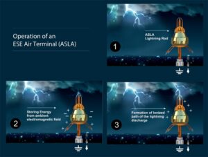
- Create a path to dissipate static discharge voltages (lightning or other forms) to the earth.
- Provide the required interface to ground in all soil conditions and provide high-fault current capacity on low, medium, and high voltage substations, towers, and power distribution applications.
Rod Earthing Functions
Human Protection
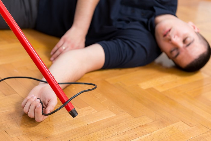
Electrical equipment has exposed or covered metal parts with protective insulation. Earth rods protect humans from direct or indirect contact from exposed metal parts with damaged insulation even after the insulation wears off.
Protection to LV Installation
Reduces common-mode disturbances external to the LV installation, for example, 50/60 Hz overvoltage in the event of:
- MV/LV transformer breakdown
- Overvoltage due to lightning
In the case of LV breakdown, the potential of the power system rises concerning the earth. Without grounding, it creates a risk for the equipment and workers in the TT system. Apart from a lightning strike, the power system encounters pulsating overvoltage on all live conductors. It may result in high EMC risk; therefore Earthing systems like Rod Earthing is required. Let’s understand it’s types in detail.
Types of Rod Earthing
The effectiveness of an earth rod is influenced by its resistance and conductivity properties. These characteristics determine the rod’s ability to carry fault currents safely to the ground, a critical aspect of any grounding system. Let’s explore these properties in detail for pure copper, copper bonded, and stainless-steel earth rods.
Chemically Charged Pipe Electrodes
Unlike traditional earth rods, ACRE employs a unique mechanism that utilizes a hollow copper shaft filled with natural earth salts and desiccants. This design takes advantage of the hygroscopic nature of these materials to absorb moisture from the surrounding environment. The moisture reacts with the salts to create an electrolytic solution, which is then continuously released into the surrounding soil. This process not only maintains an optimal moisture level around the electrode but also enhances the soil’s ionic content, thereby reducing ground resistance and improving the overall efficiency of the grounding system.
This type of Rod Earthing is particularly effective in challenging environmental conditions where traditional grounding methods may falter. Its ability to generate and maintain an electrolytic solution makes it an ideal choice for areas with dry, sandy, or rocky soil conditions, where maintaining consistent ground moisture and conductivity is difficult. Furthermore, the ACRE’s design ensures that it becomes more effective over time, as the continuous interaction between the electrolytic solution and the soil enhances the ground’s conductive properties.
This technology is beneficial for critical infrastructure and industrial applications, where reliable grounding is essential for operational safety and efficiency. Chemically Charged Pipe Electrode’s resilience to environmental changes, coupled with its self-improving nature, offers a long-term grounding solution that minimizes maintenance needs and maximizes performance reliability. By addressing the limitations of conventional grounding rods through its innovative design, this rod provides an effective solution for a wide range of grounding applications. Its ability to adapt to and improve the surrounding soil conditions makes it a valuable addition to modern grounding systems, ensuring safety and reliability in electrical installations across diverse environments.
Design of Rod Earthing
In grounding systems, a metallic object is seamlessly integrated with the earth through an earth electrode system, ensuring electrical safety and stability. The efficacy of this system, characterized by the strength of the fault current, is directly influenced by the type of Earthing system deployed. Adherence to safety standards, such as maintaining contact voltage below 50 V as recommended by UL for AC systems, is paramount. This involves connecting the exposed metallic parts of electrical equipment to protective earth (PE) conductors, which in turn are linked to the earth, establishing a comprehensive Earthing arrangement.
Guidelines set forth by the National Electric Code (NEC) mandate that grounding electrodes exhibit a resistance-to-ground (Earth) of less than 25 ohms, explicitly prohibiting the use of aluminium electrodes in grounding, as per standards 364 and NF C 15-100 (1923).
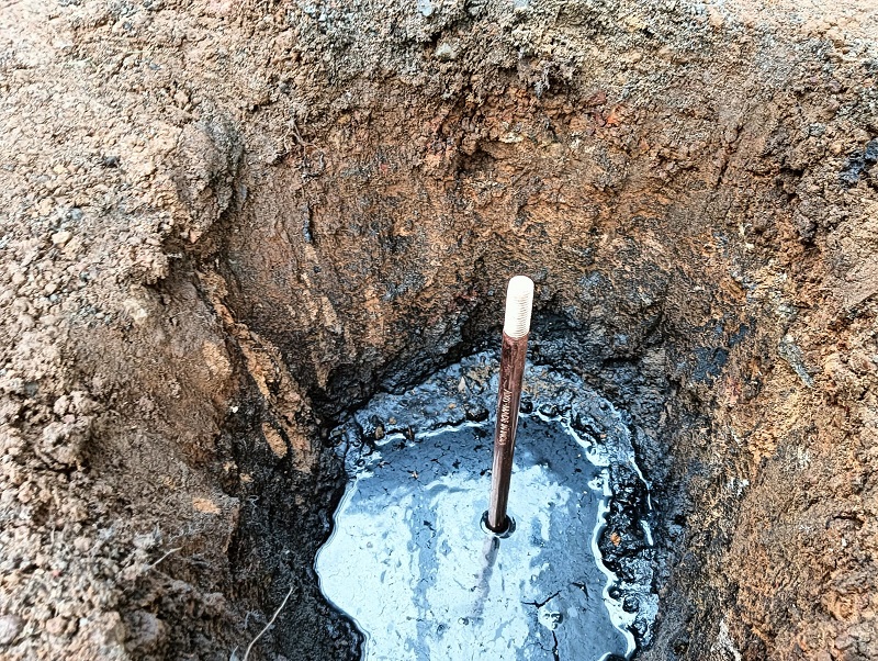
To ensure safe, dependable, and enduring Earthing protection, earth rods must be meticulously selected based on the corrosive nature and electrical conductivity of the soil, alongside the rod’s mechanical durability to endure the rigors of installation without deformation, particularly at the head when driven into the ground.
For achieving the requisite depth and maintaining enduring electrical connectivity, copper couplers are utilized to link multiple earth rods together. This technique allows for reaching deeper, lower resistivity soil layers, enhancing the grounding system’s effectiveness.
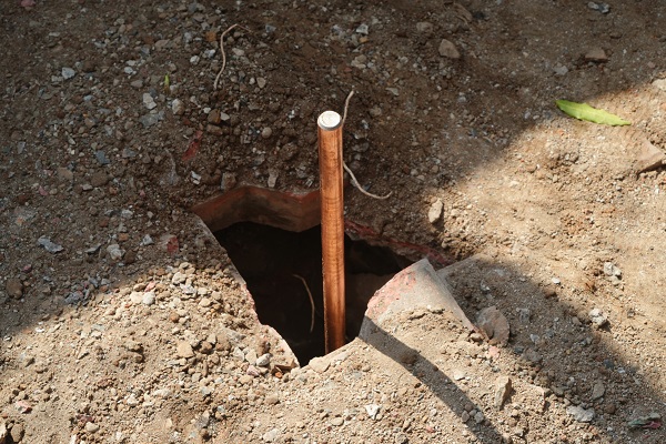
Vertically-driven earth rods are recognized as the most efficient, particularly favored in compact substation areas or in conditions of low soil resistivity.
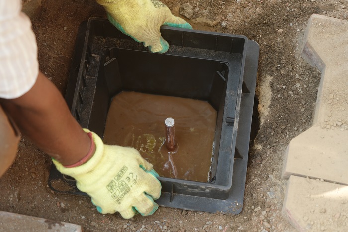
The performance of an earth rod is verified through a current probe encircling the conductor leading to the earth or ground rod. Any discrepancy, such as leakage current, is readily identified, indicating a potential flaw in the grounding system. This method underscores the critical nature of rigorous testing to ensure the grounding system’s integrity and functionality.
Types of Earth Electrodes
Rod Earthing
As discussed above, these rods are standard driven rods or copper-clad rods used as grounding devices. They are made of relatively low carbon steel, are 8 to 10 feet long, and have 254 Microns as per UL Standard. NEC mandates that that driven rod must be at least 8 feet in length, and it must be in direct contact with the soil.
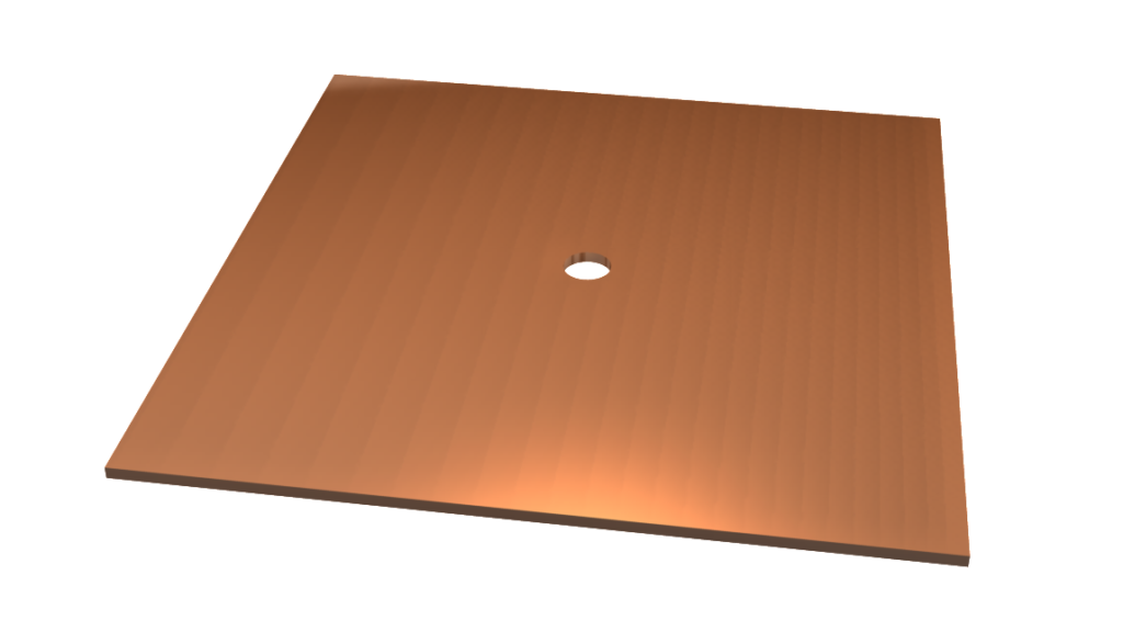
Grounding Plates
These thin copper plates are placed in direct contact with the earth under poles or supplementing counterpoises. NEC advises that these plates should have at least 2 ft. of surface area exposed to the surrounding soil. The ferrous materials must be at least .20 inches thick. The non-ferrous materials (copper) need a thickness of only .060 inches. These should be buried at least 30 inches below grade level. The surface area of grounding plates increases over a driven rod; the zone of influence is relatively small. The zone of influence of a grounding plate can be as small as 17 inches.
Ufer Ground or Concrete Encased Electrodes
These electrodes channelize the faulty current to the earth through the concrete. These foundations are used when the concrete of the structure is in direct contact with the earth, i.e. there are no plastic barriers. One example is the concrete surrounding ammunition bunkers, building foundations. For building foundations, they consist of any concrete-encased electrode like the rebar (0.500 inches in diameter) or a wire or wire mesh in the concrete. There would be a direct metallic connection from the service ground to the rebar buried inside the concrete. The process depends on the conductivity of the concrete and the large surface area, which usually provides a grounding system to handle very high current loads.
But as per NEC guidelines, they use 20 feet (minimum) long No. 4 AWG copper wire that is encased in a 2 inches (minimum) of concrete; the zone of influence is not increased. So the resistance to the ground is only slightly lower than the wire without the concrete. As concrete retains a substantial amount of water, the moisture in it superheats and expands rapidly. A high current may cause steaming creating cracks. Cracked concrete pieces do not let the copper wire contact the surrounding soil. It increases the resistance-to-ground of the electrode. Therefore, relatively small electrical faults may damage the electrodes, which is risky to the building.
Besides, Ufer groundings are impossible to test unless there is a fault with a high current. Isolating the concrete slab to test resistance-to-ground is nearly impossible. Here’s a detailed blog on Ufer Grounding.
Water Pipes
Water pipes with plastic insulators are in use as grounding electrodes for a long time. Plastic insulators are used usually by city water departments in pipelines. It prevents the flow of current and reduces the corrosive effects of electrolysis. Also, the plastic or tar coating makes them unreliable. Therefore, NEC guidelines mandate that at least one additional electrode must be installed with the water pipe.
Conclusion
The selection of an earth rod is a critical decision that impacts the effectiveness and durability of grounding systems. Each type of earth rod—pure copper, copper bonded, and stainless steel carries its own set of specifications, advantages, and considerations. The choice depends on a balance of factors including conductivity requirements, environmental conditions, budget constraints, and risk of theft. Understanding the specific earth rod specifications allows for an informed decision, ensuring that the chosen rod meets the unique needs of each application. Ultimately, all types of earth rods play an integral role in grounding systems, with their importance varying based on the specific requirements of the installation.