Earthing Design involves conducting a thorough site survey, considering local soil conditions, choosing the appropriate earthing electrodes and conductors, and complying with applicable codes and standards. By following these steps, you can design an earthing system that provides effective protection against electrical hazards and ensures the safe and reliable operation of the electrical system.
Standards for Earthing Design
In this article, we use several Earthing Design standards including:
-
- IEC 62305 Part 3: Protection against lightning – Part 3: Physical damage to structures and life hazard.
- BS 7430: Code of practice for protective earthing of electrical installations
- IS 3043: Code of Practice for Earthing
There are several reasons why it is important to design earthing systems according to international standards such as IEC 62305. One of the main reasons is safety. These standards provide guidelines for ensuring that earthing systems are accurately designed and installed, which can help prevent electrical accidents and injuries. These guidelines include recommendations for the materials that should be used for earthing, the methods for installing earthing systems, and the methods for testing earthing systems to ensure that they are functioning properly.
What are the Steps for Earthing Design?
Here are some general steps you can follow when designing an earthing system:
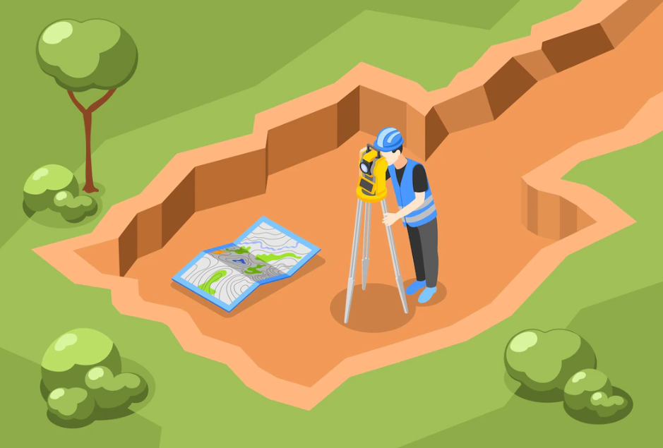
A) Conduct a site survey: The first step in designing an earthing system is to conduct a thorough site survey to gather information about the building or structure, the electrical equipment, and the local soil conditions. This information will help determine the size and layout of the earthing system.
B) Determine the Earthing System requirements: Based on the information gathered during the site survey, you will need to determine the earthing system requirements, including the type and size of earthing electrodes, the spacing and placement of the electrodes, and the type and size of earthing conductors.
C) Design the Earthing System: Using the information gathered during the site survey and the earthing system requirements, you can begin to design the earthing system. This will involve creating a detailed layout of the earthing electrodes and conductors, and specifying the materials and components.
D) Review and refine the Design: After completing the initial design, it is important to review and refine the design to ensure that it meets all applicable codes and standards and that provides adequate protection against electrical hazards. This may involve making modifications to the layout or components of the earthing system or conducting additional site surveys to gather more information.
How to conduct a Site Survey while designing my Earthing System?
When conducting a site survey to design an earthing system, you will need to gather information about the building or structure, the electrical equipment and the local soil conditions. Here are some general steps you can follow to conduct a site survey:
- Gather information about the building or structure: You will need to collect information about the size and layout of the building or structure, including the number and type of rooms, the type of electrical equipment that will be used, and the location of electrical panels and outlets.
- Gather information about the electrical equipment: You will also need to gather information about the type and size of the electrical equipment that will be used, including the voltage and current ratings, the type and size of conductors, and the location of grounding points.
- Gather information about the local soil conditions: To design an effective earthing system, you will need to know the local soil conditions, including the type and composition of the soil, the moisture content, and the electrical resistivity. This information can be obtained from soil surveys or other sources, or can be determined through on-site testing.
- Create a detailed survey report: Once you have collected all the necessary information, you will need to create a detailed survey report that summarizes the information and provides the basis for designing the earthing system. This report should include a description of the building or structure, a list of the electrical equipment, and information about the local soil conditions.
What on-site testing will determine Soil Conditions?
The soil resistivity is an important factor that can impact your choice of earthing electrode. Soil resistivity is a measure of the electrical resistance of the soil, and is typically expressed in ohm-meters (Ω-m). The lower the soil resistivity, the more conductive the soil is, and the more effective the earthing system will be.
There are several on-site testing methods that you can use to determine the suitability of the soil for earthing. Some common methods include:
- Soil resistivity testing: This involves using a soil resistivity meter or tester to measure the electrical resistance of the soil. The lower the resistance, the more conductive the soil is, and the more suitable it is for earthing.
- Soil auger testing: This involves using a soil auger or penetrometer to take samples of the soil at different depths. The samples can then be tested in a laboratory to determine their composition, moisture content, and other properties that can affect the suitability of the soil for earthing.
- Soil coring testing: This involves using a soil coring device to extract samples of the soil from different depths. The samples can then be tested in a laboratory to determine their composition, moisture content, and other properties that can affect the suitability of the soil for earthing.
- Soil probe testing: This involves using a soil probe or rod to measure the resistance of the soil at different depths. The resistance can be used to determine the conductivity of the soil and its suitability for earthing.
There are six basic test methods to measure Earth Resistance:
- Four-point method (Wenner method)
- Three terminal methods (falloff potential method/ 68.1% method)
- Two-point method (dead earth method)
- Clamp-on test method
- Slope method
- Star delta method
It is important to note that the suitability of the soil for earthing can vary depending on factors such as the type and composition of the soil, the moisture content, and the electrical resistivity. Thus, it is important to conduct thorough on-site testing to gather as much information as possible about the soil conditions.
Can Soil Resistivity impact my choice of Earth Electrode?
When choosing an Earthing Electrode, it is important to consider the soil resistivity at the site where the earthing system will be installed. If the soil resistivity is low, you may be able to use a smaller or less expensive earthing electrode, as the soil will be able to conduct electricity more effectively. But, if the soil resistivity is high, you may need to use a larger or more expensive earthing electrode to provide adequate protection against electrical hazards.
In general, Earthing Electrodes should be sized and selected based on the expected current flow through the earthing system. The current flow will depend on factors such as the type and size of electrical equipment, the local soil conditions, and the applicable codes and standards. By considering these factors and choosing the appropriate earthing electrode, you can ensure that your earthing system provides adequate protection against electrical hazards.
Once you have determined the earthing system requirements, you can choose the appropriate earthing electrodes. There are several types of earthing electrodes available, including rod electrodes, plate electrodes, and pipe electrodes. The type and size of earthing electrodes you choose will depend on your specific situation and the requirements of the earthing system.
IEC 62305, BS 7430 and IS 3043 provide guidance on the minimum requirements for earthing systems, including the type and size of earthing.
Earthing Design – Layout of the Earthing Electrodes and Conductors

To create a detailed layout of the earthing electrodes and conductors for your earthing design, you will need to use the information gathered during the site survey and the earthing system requirements to determine the placement and spacing of the electrodes, and the size and type of conductors.
Determine the placement and spacing of the earthing electrodes: This will involve deciding where to locate the electrodes, and how far apart they should be. The location of earthing electrodes is determined based on many factors, including the size and layout of the building or structure, the type and size of electrical equipment that will be used, and the local soil conditions. There is no specific formula that can be used to determine the exact location of earthing electrodes, as the best location will depend on the specific situation and requirements of the earthing system. In general, the placement of earthing electrodes should be based on the expected current flow through the earthing system. By considering these factors and choosing the appropriate earthing electrodes, you can ensure that your earthing system provides adequate protection against electrical hazards.
Choose the appropriate Earthing Conductors: Once you have determined the placement and spacing of the earthing electrodes, you can choose the appropriate earthing conductors. There are several types of earthing conductors available, including copper wire, copper tape, and copper-clad steel wire. The type and size of earthing conductors you choose will depend on your specific situation and the requirements of the earthing system.
Create a detailed layout of the earthing electrodes and conductors: Using the information about the placement and spacing of the earthing electrodes, and the type and size of earthing conductors, you can create a detailed layout of the earthing system. This will typically involve creating a plan or diagram that shows the location of the electrodes and conductors, and the connections between them. The separation distance for earthing conductors is the distance between two adjacent earthing conductors. In general, the separation distance should be sufficient to ensure that the earthing conductors can function properly and provide adequate protection against electrical hazards. If the components of an earthing or lightning protection system are too close to each other, they can interfere with each other’s operation. For example, if the components are not adequately separated, the currents flowing through the earthing system may interfere with the operation of the lightning protection system, reducing its effectiveness at dissipating lightning strikes. Similarly, if the components of the earthing system are too close together, they may not be able to dissipate electrical currents effectively, which can increase the risk of electrical accidents and damage to buildings and structures. Therefore, maintaining a minimum separation distance between the components of an earthing or lightning protection system is important to ensure that the system is effective.
Review and refine the layout: Once you have created a detailed layout of the earthing electrodes and conductors, it is important to review and refine the layout to ensure that it meets all applicable codes and standards, and that it will provide adequate protection against electrical hazards.
Common pitfalls with Earthing Design

There are several common pitfalls with earthing design that can lead to problems or deficiencies in the earthing system. Some of the most common pitfalls include:
- Not conducting a thorough site survey: A thorough site survey is essential for designing an effective earthing system. If the site survey is incomplete or inadequate, the earthing system may not provide adequate protection against electrical hazards.
- Not considering local soil conditions: The local soil conditions can have a significant impact on the effectiveness of an earthing system. If the soil is not conductive enough, the system may not provide adequate protection against electrical hazards.
- Not choosing the appropriate earthing electrodes: The type and size of earthing electrodes are important factors in the design of an earthing system. If the wrong type or size of earthing electrodes are chosen, the system may not provide adequate protection against electrical hazards.
- Not considering applicable codes and standards: Earthing systems must comply with a variety of codes and standards, such as the National Electrical Code (NEC) and the International Electro-technical Commission (IEC) standards. If the earthing system does not comply with these codes and standards, it may not provide adequate protection against electrical hazards.
- Not conducting regular maintenance: Earthing systems require regular maintenance in order to function properly. If the system is not maintained, it may become less effective over time, and may not provide adequate protection against electrical hazards.
Next time you are Designing your Earthing System, you can contact the experts at Axis to help you. With 25+ years of experience and a team of 35+ engineers, we live and breathe Earthing & Lightning Protection.
Thank you for reading the blog, Axis is a leading manufacturer and supplier of Electrical Components to over 80+ Countries. . You can also watch our videos by our experts – click here.
Follow us on LinkedIn for regular updates on our Products!


