Earth resistance refers to the resistance an earth electrode offers to the current flowing into the ground. Ideally, this resistance should be zero to allow fault current to flow quickly into the earth. However, achieving zero resistance is practically impossible. The earth resistance value is different in different locations. Earthing value as per Indian Standard gives a tolerable resistance value for different structures and is mainly depending on the soil resistivity.
According to IS 3043, the earthing resistance value is mainly dependent on three factors:
1) The resistance of the earth electrode
2) The soil resistivity
3) The contact resistance between the electrode surface and the soil
The other two factors are considered negligible compared to the soil resistivity therefore they are practically avoided. This is the reason why we mainly focus on soil resistivity measurement when we consider the earthing value as per Indian Standard. The resistance of the soil depends on different factors such as moisture content of the soil, chemical composition, concentration of salts dissolved in the water content, grain size and closeness of packing. Soil temperature also has importance in the soil resistivity value if it is very low and close to freezing temperatures.
Moist soil that can hold moisture throughout the year is preferable for the installation of earthing system. Wet marshy ground, clay, loamy soil land, arable land, or land with loam mixed with small quantities of sand, gravel and stones, peat etc are the best soil choices for earthing purposes. Land with entirely dry sand, gravel chalk, limestone, granite, and very stony ground should be avoided if possible.
Free Book on Lightning Protection Standards

Permissible Earth Resistance Value as per Indian Standard
The permissible earth resistance values are identified with reference to the various base values specified in the Indian Electricity Rules:
– The recommended safe touch potential value is supposed to be 523 volts
– Ifault = maximum current in fault conditions
– Resistance = Touch voltage/Fault current
For a substation of 100 KVA transformer:
– Maximum Fault current = 100 * 100/4 = 2500 A, which can be taken as 2000A
– Then the permissible earth resistance value = 523/2000 = 0.26ohms
To obtain such a low value for earthing resistance, the quality of the earthing system must be excellent, and the expenditure will be very high. Hence a nominal value of 1ohm is taken for practical purposes. The following are the permissible resistance values for different facilities:
a) Power stations – 0.5 ohms
b) EHT stations – 1.0 ohms
c) 33KV substations – 2 ohms
d) DTR structures – 5 ohms
e) Tower foot resistance – 10 ohms
These are taken as the reference for permissible values for earthing resistance. Various methods are used to obtain a minimum resistance value. The usual practice is to deep drive the earth electrode below the ground level to get stable moist soil. Thus, the earth resistance value remains unaltered even when the upper layers of the soil are dried out. At times, it is identified that the earth resistance value does not improve enough even if the electrodes are buried deep inside the soil. This is because the soil resistivity is very high at such locations. In such cases, we can use salt, charcoal or chemical earthing compounds to bring down the earth resistance value to the desired level.
Techniques for Reducing Soil Resistivity
Soil treatment is the way to minimize earth electrode contact resistance in special or difficult locations.
In the past, people used common salt and charcoal to fill earth pits and reduce soil resistivity while increasing moisture content. Today, engineers often choose Bentonite or Marconite in rocky and hard terrain because they reduce soil resistivity more effectively than salt and charcoal. Whether using deep-driven vertical electrodes or radially laid earthing strips, Bentonite and Marconite improve the electrode’s contact with the ground.
Keep in mind—high moisture content doesn’t always mean low soil resistivity. Sometimes, earth electrodes driven directly into riverbeds or streams show very high earth resistance. If the water is pure the resistivity can be high unless the soil contains sufficient elements to form a conducting electrolyte. The high moisture content or water availability can help increase the solubility of existing natural elements or artificially introduced compounds to improve soil conductivity.
Another means to increase the earthing capacity is to increase the number of earthing electrodes. But at times even this seems to fail. This usually happens in the case of soils with extremely high resistivity. The easiest and immediate method to reduce the soil resistivity in such cases according to IS 3043 is to dissolve substances like sodium chloride ( NaCl), calcium chloride ( CaCl ), sodium carbonate ( Na2CO3 ), copper sulphate ( CuS04 ), salt, and soft coke, and salt and charcoal in suitable proportions. With average or high moisture content, these agents form a conducting electrolyte surrounding the earth electrode.
Conclusion
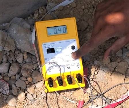
Engineers first measure the earth resistance at a site and compare it with the standard values before designing the earthing system. They design the system to maintain the Earthing value as per Indian Standard. Based on the resistance value, they treat the soil during the installation of the earth electrode. They apply salt and other earthing compounds in the pit or around the electrode. Then, they fill the basin with water multiple times, allowing the soil to soak thoroughly. This process creates a wet cylindrical space around the electrode’s entire length, which significantly lowers the earth resistance.
Generally, this improved conductivity of soil lasts for many years. But still, it is recommended to measure the earth resistivity of the electrode yearly or half-yearly and take necessary action towards re-treatment of the soil if the resistivity is increased above the desired value.
In addition, ensuring proper bonding, periodic testing, and compliance with IS 3043 and other relevant standards plays a crucial role in maintaining a safe and efficient earthing network. A well-designed and regularly maintained earthing system not only protects electrical installations from faults and surges but also ensures personnel safety, system reliability, and long-term equipment performance. Therefore, regular inspection, documentation, and preventive maintenance are vital components of any robust earthing management program.

Thank you for reading the blog, Axis is a leading manufacturer and supplier of Electrical Components to over 80+ Countries. Talk to our industry expert by visiting our contact us section. You can also watch our videos by our experts – click here.
Follow us on LinkedIn for regular updates on our Products!

FAQ
Q1. What is the permissible earthing resistance value as per IS 3043?
A: As per IS 3043, the permissible earthing resistance value depends on the type of installation. Typically, it is 0.5 ohms for power stations, 1 ohm for EHT substations, 2 ohms for 33 kV substations, 5 ohms for distribution transformer structures, and 10 ohms for tower foot resistance. In practical applications, a value of 1 ohm or less is generally considered safe and effective for most electrical systems.
Q2. Why is soil resistivity important in determining earthing value as per Indian Standard?
A: Soil resistivity plays a critical role in determining earthing resistance because it directly affects how easily fault current flows into the ground. Factors like moisture content, temperature, salt concentration, and soil composition influence resistivity. Lower soil resistivity ensures better conductivity, which helps achieve the desired earthing value as per IS 3043 and improves overall electrical safety.
Q3. How can earth resistance be reduced to meet Indian Standard requirements?
A: Earth resistance can be reduced by using techniques such as deep driving of electrodes into moist soil, increasing the number of electrodes, and applying soil treatment compounds like Bentonite, Marconite, salt, and charcoal. These methods improve soil conductivity and help achieve the recommended earthing resistance values as per Indian Standards.
Q4. How often should earthing systems be tested and maintained as per IS standards?
A: As per best practices aligned with IS 3043, earthing systems should be tested at least once every year or half-yearly depending on site conditions. Regular testing helps identify increased resistance due to soil changes and ensures timely soil re-treatment, system maintenance, and compliance with Indian earthing standards.