What is a Single Line Diagram?
A single line diagram also called the one-line diagram is a symbolic or graphical representation of a three-phase power system. It has a diagrammatic representation of all the equipment and connections. Standardized schematic symbols represent electrical elements such as circuit breakers, transformers, bus bars, and conductors, making them easy to read and understand. In a single line diagram, instead of representing each of the three phases with separate lines, a single conductor represents all three phases. A single line diagram makes it easy to understand an electrical system, particularly in the case of complicated systems in substations. It helps in a detailed study and evaluation of the system and its efficiency.
Advantages of Single Line Diagram:
- Gives an overall understanding of the system and eases evaluation.
- It simplifies the troubleshooting process and makes it faster.
- It further ensures the safety of personnel and makes maintenance more convenient.
- It ensures a safer and more reliable operation of the system.
Important symbols for a Single Line Diagram:
In power substations, operators disconnect a part of the system for general maintenance and repairs using an isolating switch or an isolator. An isolator is a switch designed to open a circuit under no load. For example, if the entire substation is divided into five sections, operators can disconnect each section with the help of an isolator for maintenance.
Busbar: A busbar is an assembly of bus conductors with associated connection joints and insulating supports. It is a grounded metal enclosure containing factory-mounted, bare or insulated conductors, usually copper or aluminium bars, rods or tubes.
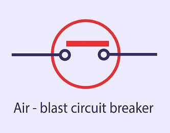
Circuit breaker: A circuit breaker is a component that can open or close a circuit under normal and fault conditions. It is designed for manual operation under normal conditions and automatic operation under fault conditions. It is a special type of switching device that operates safely under high current conditions. Operators use it to disconnect and reconnect different parts of the power system for protection and control.
Transformers: Transformers play a vital role in power transmission and distribution. They step up or step down the voltage. Power stations typically use a step-up transformer to increase the generated voltage to a higher value. At subsequent substations, a step-down transformer reduces the supply voltage before delivering it to the utilization end.
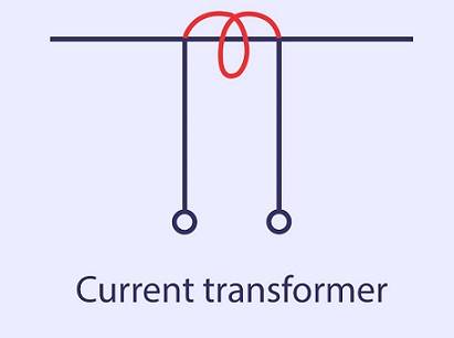
A current transformer is a step-up or step-down transformer that multiplies the current to a known ratio. For example, if a current transformer has a rating of 100/5A, the current on the primary side is 100A and the secondary is 5A. It is a type of instrument transformer. Another type of instrument transformer is the voltage transformer or potential transformer.
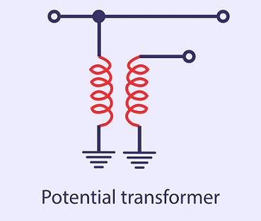
A potential transformer is an instrument transformer used for protection and measurement purposes. It measures the high alternating voltage in a power system. It is usually a step-down transformer with a lesser number of windings on the secondary side.
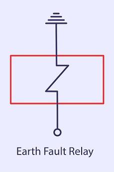
Protective relays: The primary function of protective relays in substations is to cause prompt removal of any element from the service when it suffers a short circuit. Also, it protects when part of a system starts to operate in an abnormal manner that might cause damage or interfere with the normal operation of the complete system. There are different types of protection relays mainly based on their characteristics, logic, actuating parameters and operation mechanism.
Above, we have discussed some of the important components we see in a single line diagram. There are more components used in an electrical system that have various applications.
Example of a Single Line Diagram
Now we shall see an example of a single line diagram of an 11kV/400V indoor substation and its explanation.
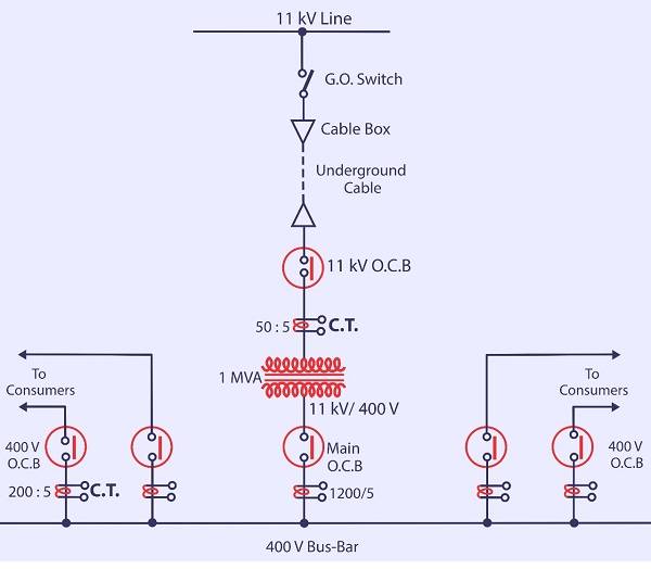
The utility taps the 3-phase, 3-wire 11 kV line and brings it to the gang operating switch installed near the substation. The gang-operated switch (G.O. switch) consists of isolators connected to each phase of the 3-phase line. From the G.O. switch, the system brings the 11 kV line to the indoor substation as an underground cable. The cable connects to the high voltage or primary side of the transformer (11 kV/400 V) via the 11 kV Oil Circuit Breaker. The transformer steps down the voltage to 400 V, 3-phase, 4-wire.
A single-phase residential load connects between any one phase and neutral. A 3-phase, 400 V motor load connects across the 3-phase lines directly. Operators install current transformers at suitable places in the substation circuit and supply them for metering and indicating.
The secondary of the main transformer supplies the busbars through the main circuit breaker. From the busbars, the system provides 400V, 3-phase, 4-wire supply to customers via the 400V circuit breaker. The voltage between any two phases is 400V, and the voltage between one phase and neutral is 230V.

This article is part of our series of articles on Lightning Protection, Surge Protection & Earthing, you can read more with the following links:
Surge Protection Devices (SPD)
Lightning Protection Zones and their Application to SPD Selection
Thank you for reading the blog, Axis is a leading manufacturer and supplier of Electrical Components to over 80+ Countries. Talk to our industry expert by visiting our contact us section. You can also watch our videos by our experts – click here.
Follow us on LinkedIn for regular updates on our Products