Earthing, also known as grounding, is a fundamental safety measure in electrical systems. It’s a method that connects the neutral points of a system to the earth, providing an alternative path for electrical energy to discharge safely during a fault. This prevents dangerous potential build-ups in exposed conductive materials. A well-designed earthing system has low impedance, which ensures sufficient current can flow through safety devices and disconnect from the supply during a fault. This safeguards both people and electrical devices from electrical hazards and current leakage. In this blog we will understand the the concept of Types of Earthing, focusing on Plate Earthing, Diagram of Plate Earthing, it’s procedure and applications.
Now, let’s delve deeper into the concept of Plate Earthing, one of the types of earthing systems.
What is Plate Earthing?
Plate Earthing is a method where a plate made of galvanized copper or iron is buried vertically at least 3 meters below ground level. This plate connects all conductors to the earth, providing a path for electrical discharge. The Diagram of Plate Earthing typically illustrates this setup, showing the plate’s position in relation to the ground level and the conductors it connects.
The Plate Earthing Diagram also often includes the dimensions of the plate. For instance, a copper plate used in this method typically measures 600mm x 600mm x6.35mm. The plate’s size and material can vary based on specific requirements, but the principle remains the same, to provide a safe path for fault current to the earth.
Free Book on Lightning Protection Standards

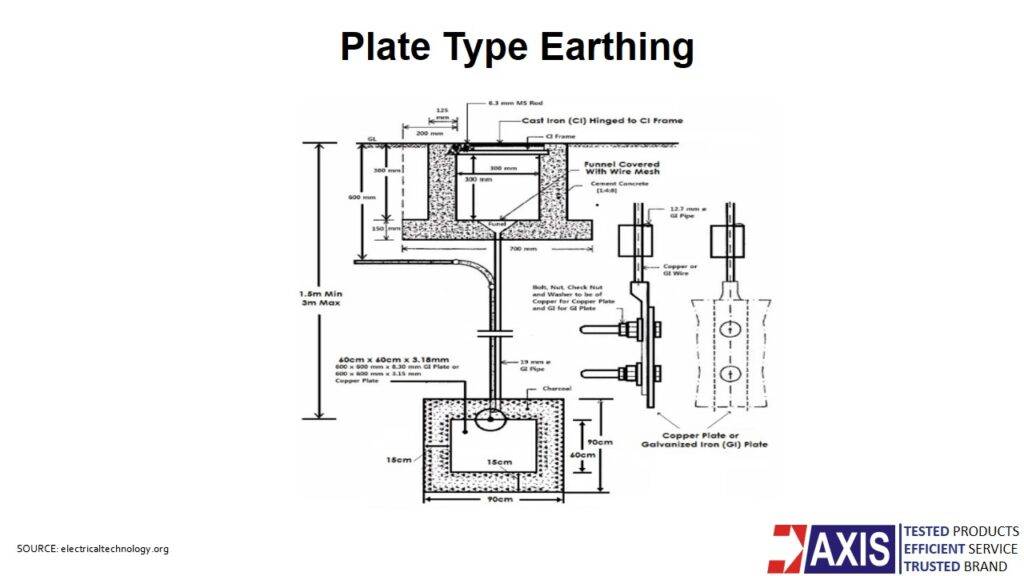
Plate Earthing Diagram’s Explanation
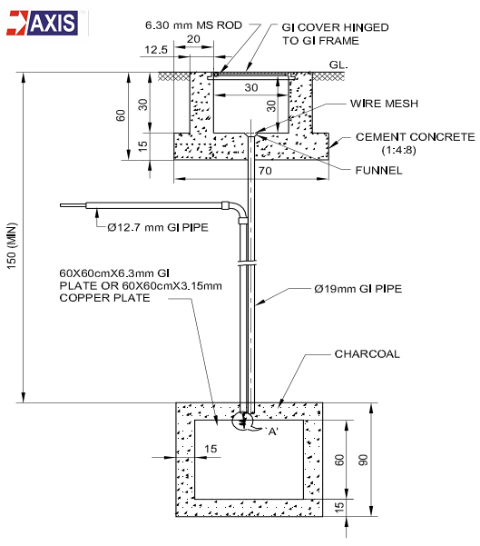
The diagram of plate earthing shows a plate electrode made from either galvanized iron or steel (minimum thickness 6.3 mm) or copper (minimum thickness 3.15 mm). The plate must measure at least 60 cm by 60 cm.
Installers bury the plate in the ground and surround it with alternating layers of charcoal and salt. The charcoal retains moisture, which helps maintain low earth resistance.
They connect a galvanized iron strip to the plate and extend it above ground to link the electrode to the electrical system.
The diagram also includes a pipe used to water the soil around the plate, which helps keep the surrounding area moist for effective earthing.
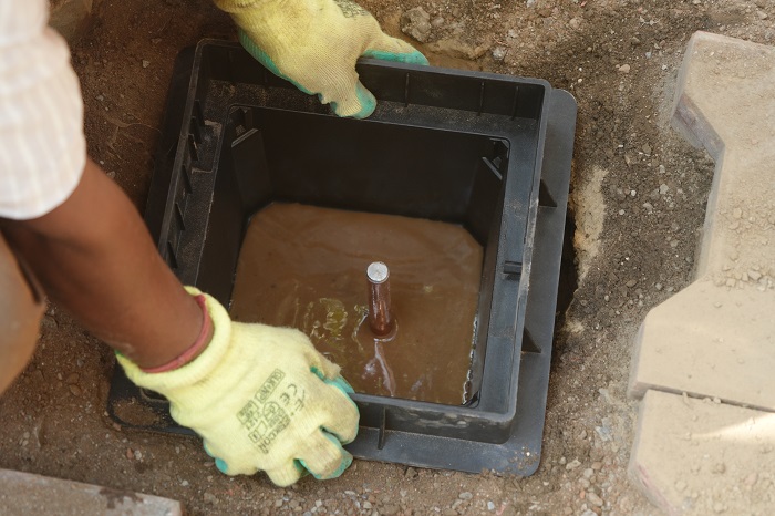
To ensure easy maintenance, they construct an inspection chamber around the earth pit for regular checks and upkeep of the earthing system.
Plate Earthing Procedure
The procedure for Plate Earthing involves several steps, often illustrated in a Diagram of Plate Earthing:
- Earth Pit: Engineers excavate the earth pit at a suitable location in the substation. The pit must measure at least 900mm × 900mm and go 3 meters deep below the surface.
- Plate Electrode: They use a GI plate of at least 600mm × 600mm with a thickness of 6.3mm. If they opt for a copper plate, it must be at least 3.15mm thick. They surround the plate with alternating layers of charcoal and salt.
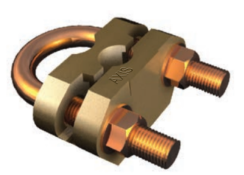
- Earthing Connection: Technicians fix and weld galvanized iron strips to the plate at two points. To avoid high system resistivity, they ensure all connections are strong and secure.
- Water Connection: They install a pipe at the top to keep the soil around the plate moist. A wire mesh covers the pipe, and they pour water through it. Then, they fill the pit with soil free from stones.
- Inspection Chamber: They build a brick inspection chamber over the pit on a P.C.C layer. The chamber includes a top cover with cast iron hinges fixed to a CI frame.
Other Types of Earthing
Apart from Plate Earthing, there are other types of earthing systems as well. These include Pipe Earthing, Rod Earthing, and Chemical Earthing. Each of these methods has its unique characteristics and applications, but all aim to provide a safe path for electrical discharge.
Pipe Earthing: This involves burying a galvanized steel perforated pipe vertically, connecting all electrical conductors to the ground. The depth of the pipe depends on soil conditions. This is a cost-effective earthing method. Read our blog to know more about Pipe Earthing.
Rod Earthing: Here, a copper rod or galvanized steel hollow section is buried vertically at least 2.5 meters deep. This method reduces the earth’s resistance to the desired value, similar to pipe earthing.
Chemical Earthing: This method involves applying a chemical compound to layers of charcoal and salt, which are then buried. The procedure is similar to pipe earthing. Read our blog to know more about Chemical Earthing.
The choice of earthing type depends on various factors such as safety requirements, equipment maintenance, economic considerations, and the need for supply continuity at different voltage levels.
Standards for Earthing Systems
Earthing systems adhere to various standards, including IS 2309- 1989 (protection against lightning)
IS 3043 (Code of Practice for Earthing)
Indian Electricity Rules 1956
Central Electricity Authority Regulations (CEAR).
These standards ensure the safety and effectiveness of the earthing systems. Also, Megger for testing the resistivity of earth, welding tool kit, excavator for earth pit excavation, copper wires, pipe, coke/ charcoal and salt, PVC wires, cement, bricks, funnel and, wire mesh are the materials used for earthing.
Applications of Plate Earthing
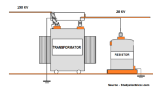
Plate earthing is used in various applications, including telecommunications, power generation, transformer neutral earthing, lightning arrester earthing, and more. It’s a versatile method that can be adapted to different environments and requirements.
Conclusion
In conclusion, electrical earthing is a vital safety measure in electrical systems. It minimizes the danger of electrical current discharge and improves lightning protection systems. Plate earthing, in particular, can prevent static charges and stray current accidents, protecting central communication, electronic, and AC power systems. The Diagram of Plate Earthing provides a clear visual representation of this method, aiding in understanding and implementation.
At AXIS, we test our products following major international standards such as IEC, BS EN, UNE, and UL & IS. We also provide design solutions including proprietary risk assessment software complying with IEC 62305 -2.
Additionally, maintaining the integrity of plate earthing systems through periodic inspection, soil treatment, and resistance testing is crucial for long-term reliability. Proper upkeep ensures stable resistance values, consistent performance during fault conditions, and adherence to IS 3043 and other international safety codes—helping protect both personnel and critical infrastructure from electrical hazards.

Thank you for reading the blog, Axis is a leading manufacturer and supplier of Electrical Components to over 80+ Countries. Talk to our industry expert and visit our contact us section. You can also watch our videos by our experts – click here.
Follow us on LinkedIn for regular updates on our Products!
Related Products
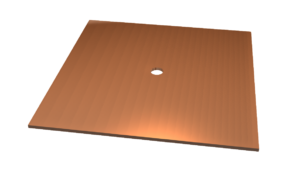
Plate Earthing
Down Conductors
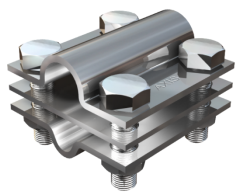
Structural Earthing
FAQ
Q1. What is plate earthing and how does it work in electrical systems?
A: Plate earthing is a grounding method where a copper or galvanized iron plate is buried vertically (typically 3 meters deep) to provide a low-resistance path for fault current to flow into the earth. It helps prevent electrical shocks, equipment damage, and fire hazards by safely dissipating excess electrical energy.
Q2. How does Axis Electricals design plate earthing systems as per IS standards?
A: Axis Electricals designs plate earthing systems in compliance with IS 3043 and IEC standards, considering factors like soil resistivity, plate size, depth, and moisture retention. Their solutions include optimized electrode design, proper material selection, and installation guidance to ensure effective and long-lasting earthing performance.
Q3. What materials and dimensions are used in a standard plate earthing system?
A: A standard plate earthing system uses a 600mm × 600mm plate, typically made of copper (minimum 3.15 mm thick) or galvanized iron (minimum 6.3 mm thick). The plate is buried in an earth pit surrounded by charcoal and salt layers to retain moisture and reduce earth resistance, ensuring efficient grounding.
Q4. Why should you choose Axis Electricals for plate earthing installation and testing?
A: Axis Electricals provides end-to-end earthing solutions, including design, product supply, installation, and testing. Their products are tested as per IEC, UL, IS, and BS EN standards, ensuring high reliability, safety compliance, and long-term performance for industrial and commercial applications.