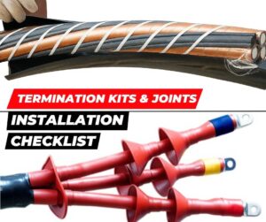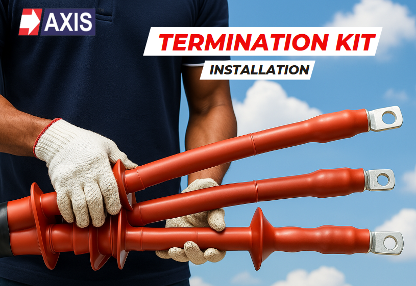
In this blog, you will learn how to install Termination Kit for medium-voltage cables.
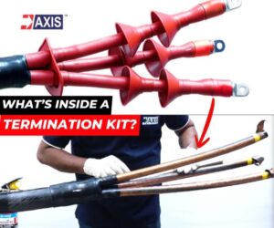
What is a Termination Kit?
Tools Required:
- Heat Gun
- Cutter
- Scrapping Tool
- Vinyl Tapes
- Ratchet Spanner
- Screwdriver
- Plug
- Measuring Tape
- Markers
Termination Kit Installation:
Step 1: Positioning of the Cable

Lay the cable in the correct position, ensuring it is stable and has adequate clearance from the ground to allow for easy installation.
Free Book for understanding Heat Shrinkable Products!

Step 2: Measuring the Installation Points

Identify the working section of the cable, where the termination will be installed. Measure the anti-tracking tube according to the manufacturer’s specifications and mark the initial length (point 1).


Add an extra 50 ± 10 mm (point 2) for future adjustments, followed by another 200 ± 10 mm marking (point 3) for the final termination step.
Step 3: Insulation Cutting

Place the metal spring coil at point 1. Using the appropriate tool, cut and strip the topmost insulation layer of the cable.
Step 4: Cutting the Armour

Expose and cut the armour layer of the cable.
Step 5: Cutting the Inner PVC Insulation


Measure 20 to 50 mm (point 1 dash) from the metal constant force spring, this length may vary between manufacturers. Now, temporarily remove the spring. Then, reposition the spring to point 1 dash. And you can strip off the inner PVC insulation layer between point 1 dash and point zero.
Talk to our engineers!
Step 6: Preparing the Inner Core


Remove the excess PVC fillers between point zero and 1 dash. ensure the fillers don’t remain inside the cable. Carefully unwrap the force spring coil and secure the copper screen with vinyl adhesive tape to prevent it from separating from the cable core.
Step 7: Exposing the Armour for Earthing

Reposition the metal force spring coil at point 2. Now, cut the outermost insulative layer of this section to expose the armour for earthing.
Step 8: Screen Earthing Process


Connect the braided earth cable to the cable’s screen. For three-core cables, use a triangular spacer. Wrap the earth cable around the cores one time, securing it with a force spring coil and vinyl adhesive tape.
Step 9: Armour Earthing

Attach another earthing cable to the exposed armour between point 1 and 2. Secure it with a force spring coil and vinyl adhesive tape.
Step 10: Mastic Wrapping Over Earthing Terminal

Wrap filling mastic tape from the exposed armour to the cable screen followed by sealing mastic tape to ensure no moisture or dust ingress. Also, apply grease over the wrapped section.
Step 11: Breakout Fitting

Slide the breakout over the mastic-wrapped section and fit it securely. Heat-shrink it using a flame gun, ensuring even heat distribution. Avoid direct flame contact to prevent the polymer from burning or charring.
Step 12: Preparing for Stress Control Tubing Installation


Measure and mark a 30 to 60 mm gap between the breakout tip and the copper screen. Use Vinyl tape to mark the position. Now strip the copper screen up to the marked point, exposing the black semi-conducting layer.
Step 13: Scraping the Semi-Conducting Layer


Mark 20 to 40 mm above the Vinyl adhesive tape as per the manufacturer’s specifications. Carefully remove the semi-conducting layer using a scraping tool so that the underlying layer remains undamaged. As per the lug supplied by the manufacturer, cut the tip of the XLPE insulation to expose the bare Aluminium or copper conductor which will go inside the lug for termination.
Step 14: Preparing the Surface for Final Tubing Installation

Smooth out the insulative layer using manufacturer-provided sandpaper. Then clean the surface with a cotton cloth and cleaning solvent to remove excess dust and debris.
Step 15: Installing the Stress Control Tube

Apply yellow (stress relief) mastic to the joints: first between the screen and the semiconducting layer, then between the insulation and semiconducting layer.
Apply grease to the insulative part and slide the stress control tube into position. Heat-shrink the tube evenly and wrap yellow mastic tape over both ends of the shrunk stress control tube.
Step 16: Installing the Anti-Tracking Tube

Insert the anti-tracking tube to cover the cable length from the breakout to the exposed conductor. Now heat-shrink the tube using the appropriate precautions.
Step 17: Inserting the Rain Shed

Slide the bottom and top rain sheds in the core. Please note that rain sheds are not used for 11 kV indoor termination kits.
Step 18: Connecting Lugs

Insert the exposed bare conductor to the lug barrel. Use a ratchet to tighten the shear head lugs until the head breaks or use a crimping tool to apply the manufacturer-specified torque for crimping lugs.
Step 19: Sealing the Lug Connection


Wrap filling mastic followed by sealing mastic tape around the bottom of the lug and the anti-tracking tube to prevent moisture ingress. Slide the lug sealing tube halfway over both the lug and anti-tracking tube and heat-shrink it evenly.
Step 20: Final Rain Shed Positioning and Shrinking

Ensure the rain sheds are properly positioned before heat-shrinking them. Apply heat evenly to avoid burning.
Step 21: Applying Phase Colour Rings

Place the phase colour rings according to the original phase colour sequence and heat them to secure them in place.
Proper installation of medium-voltage heat shrink termination kits ensures reliable insulation, mechanical protection, and long-term performance of power cables. By following correct procedures—from stress control tube installation to anti-tracking and lug sealing—technicians can achieve secure and durable terminations. Additionally, integrating busbar sleeves in your cable systems further enhances safety, minimizes electrical faults, and ensures seamless power distribution. For professional guidance and high-quality termination solutions, Axis Electrical Components offers a wide range of products and expert support to meet industry standards.
This concludes the termination kit installation process. At Axis, we have a team of over 50 engineers available to assist with designing, installing, and testing heat-shrink materials.
Our components are trusted and installed in a variety of settings worldwide, including data centers, factories, and residential and commercial buildings, ensuring the highest quality in every termination kit installation.