- Disconnect the power supply before installation.
- Use only insulated tools and equipment.
- Confirm proper grounding of the pole and cross-arm assembly.
Tools Required:
- Heat Gun
- Cutter
- Scrapping Tool
- Vinyl Tapes
- Ratchet Spanner
- Screw Driver
- Plug
- Measuring Tape
- Markers
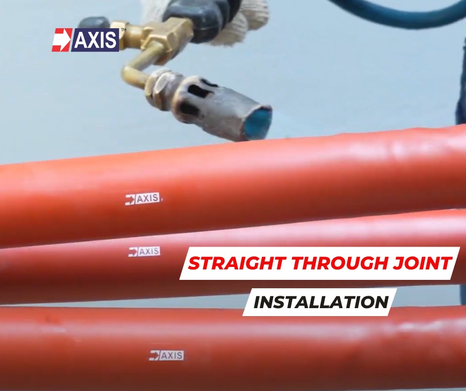
Straight Through Joint Installation Process
Step 1: Cable Identification and Length Designation

Designate one cable as the longer end, called Part A, and the other as the shorter end, called Part B.
Since the insulating tubes will overlap, the center of the joint will not have equal lengths of cable on both sides.
Step 2: Marking and Surface Preparation


The measurement varies depending on the voltage rating, that is 11kV to 33kV.
On Part A, measure and mark 1100 to 1400 millimetres from the open end, called Point 1, and then add another 200 millimetres, called Point 2.
On Part B, mark 450 to 700 millimetres called Point 3. And then, add another 100 millimetres called Point 4.
Abrade the marked sections using manufacturer-recommended silica paper to improve adhesion with the outermost insulation layer.
Step 3: Pre-Installation of Protective Tubes

Insert the four protective tubes onto one cable before jointing begins. This will avoid last-minute complications.
Arrange the tubes with the longest tube last and the shortest first, for a smooth process.
Talk to our engineers!
Step 4: Armour Removal and Insulation Stripping

Secure a metal force spring at Points 1 and 3. Cut and remove the outermost insulation layer to expose the armour.
Now strip away the exposed armour up to the metal force spring. Measure 50 to 100 millimetres from Points 1 and 3 (based on the voltage rating) and place another metal force spring.
From these points, strip the inner insulation and remove the fillers.
Step 5: Core Exposure and Metal Screen Preparation

Once the inner insulation is removed, wrap the vinyl tape at the tips of the cores to prevent unwrapping of the metal screen.
Measure 310 millimetres from end of the core, apply vinyl adhesive tape, and color-code phases using coloured tapes, for three-core cables.
Strip the metal screen from the tip of the cable to the vinyl tape mark.
Step 6: Semiconducting Layer Removal

Locate the semiconducting layer and measure 50 millimetres from the last vinyl tape. Now, apply another vinyl tape and scrape off the semiconducting layer up to this point.
Step 7: Conductor Exposure and Connector Preparation

Expose the bare conductor according to manufacturer- specified insertion length, and apply vinyl tape over the conductor for a snug connector fit.
Step 8: Stress Control Tube Installation


Polish the exposed insulation layer with manufacturer-provided sandpaper, and clean it with cotton cloth and solvent.
Apply stress relief mastic tape over half of the semiconducting and insulating layers.
Apply silicone grease on the insulation layers.
Position the stress control tube over the semi-conductive layer by 20 millimetres and heat shrink using a heat gun. Avoid excessive heating to prevent material damage.
Step 9: Semiconducting Layer Removal

Insert copper mesh onto individual cores and slide the semiconductive tube and two insulation tubes onto each core.
Join the corresponding phases using connectors, ensuring a secure fit through crimping or shear-head bolt tightening.
Step 10: Insulation Restoration Around Connectors

Apply semiconducting tape tightly around the connectors.
Apply filling mastic tape, ensuring a smooth transition between the insulation layer and the connector.
Step 11: Stress Relief Mastic Application

Wrap stress relief mastic around the step between the stress control tube and the insulation, covering a 5 to 10mm area for a smooth transition.
Apply grease on the connector and insulation area.
Step 12: Heat Shrinkable Insulation Tube Application

Pull the Insulation tube over the connector section.
Use a flame gun to heat shrink the tube securely. Repeat the process for second insulation tube.
Step 13: Semi-Conductive Tube Application

Position the semiconducting tube and heat shrink it carefully.
Apply filling mastic tape and semiconducting tape at both ends overlapping with the copper screen to ensure a continuous connection.
Step 14: Copper Screen Connection

Pull the pre-inserted copper mesh toward the centre of the joint.
Place braided earth wire around each phase core and secure it to the copper screen with a constant spring, ensuring there are no sharp edges.
Step 15: Protective Insulation Application

Slide the shorter protective tube over the joint area, ensuring it overlaps the sheath, then heat-shrink it in place.
Wrap a layer of sealing mastic at the end of the shrunk tube. Overlap with another shorter protective tube, and heat-shrink to secure.
Step 16: Armour Earthing

Connect the armour ends with a braided earth wire, tie them together using a constant spring. Ensure there are no sharp edges and add filling mastic if required.
Step 17: Final Protective Insulation Application

Apply sealing mastic to the ends of the outer sheath. Overlap with longer protective tube and heat-shrink.
Finish by wrapping sealing mastic at the end of the shrunk tube, overlapping it with another longer protective tube, then heat-shrink for a final secure seal.
Step 18: Inspection and Testing
Conduct a thorough visual inspection to confirm proper installation. Perform insulation resistance testing as per industry standards.
Step 19: Completion and Final Quality Check
Ensure all components are securely in place and verify compliance with manufacturer guidelines. The Straight Through Joint Installation Process is now complete.
This completes the Medium Voltage Heat-Shrinkable Straight Through Joint Installation. At Axis Electrical Components, we have a team of over 50 experienced engineers specializing in the design, installation, and testing of heat shrink materials. If you have any doubts, reach out to us on our website axis-india.com.