In any electrical system, things can go wrong. Wires can get damaged, insulation can crack, water can enter a switchboard, etc. When this happens, electricity starts flowing where it should not. This unwanted flow is called fault current.
Fault current is dangerous because it collects on metal parts like panels, appliances, poles, cable armour, etc. Anyone touching these parts will get an electric shock.
Earthing solves this problem. It gives fault current a low resistance path into the soil, so that it returns to the source to protect human life or equipment.
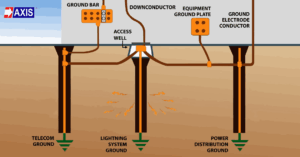
There are different types of earthing systems like plate earthing, rod earthing, strip earthing, and pipe earthing. The shapes are different, but the job is similar. Each one takes fault current safely into the soil.
To do this, every system needs a metal piece buried in the ground. This buried metal piece is called an earth electrode. It is that part of your earthing system, that actually touches the soil and carries the fault current away from your equipment. In plate earthing, this electrode is a metal plate.
How does Plate Earthing work?
In plate earthing, you place a metal plate in the ground at a fixed depth. The plate is usually buried about three meters below the surface, so it stays in contact with moist soil. This plate connects to your equipment through a copper or GI strip. The soil around the plate must stay moist because moisture keeps the resistance low. The lower the resistance, the faster the fault current moves into the soil.
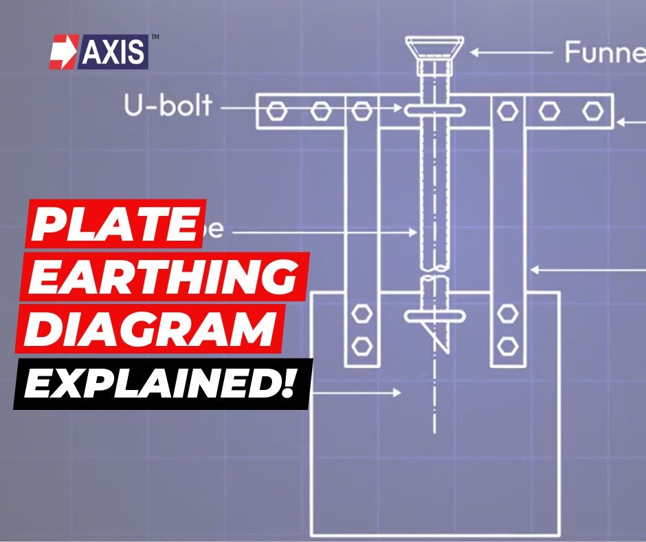
The Diagram
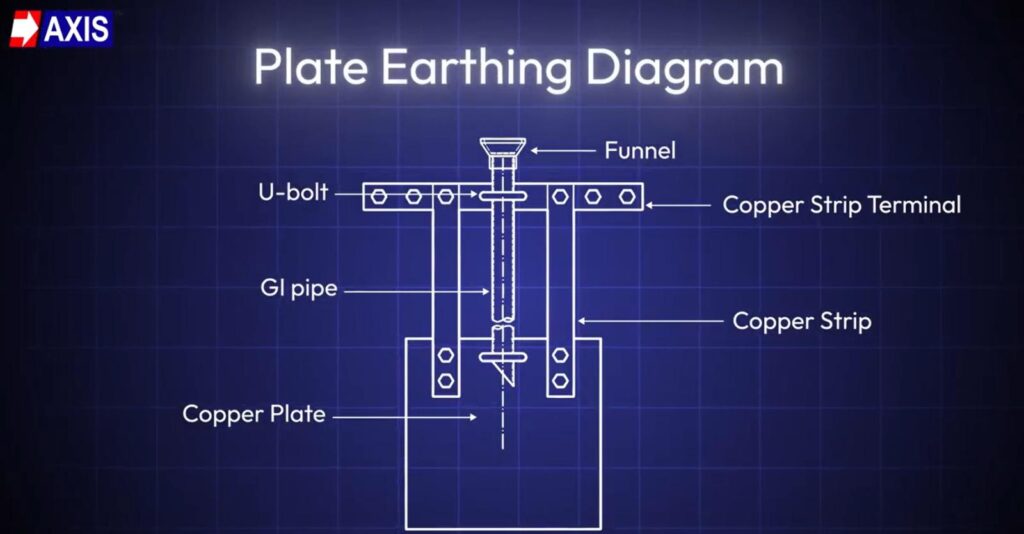
1. Starting with the plate:

A copper plate is the main electrode used in plate earthing. This is the part that goes into the soil and provides the contact area for fault current to enter the ground. When a fault happens, the current travels down the earth strip and enters the soil through this plate. The large surface area helps the current spread quickly and lowers the overall earthing resistance.
In plate earthing systems, copper plates are commonly available in sizes such as 600 mm by 600 mm, with thicknesses like 3.15 mm or 6 mm. This plate is also available Galvanised Iron, having a size of 600 by 600 mm, with thickness of 6 mm. However, you can customise it depending on your project requirement.
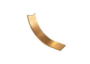
2. Copper Strip:
This strip forms the electrical path between your copper strip terminal and the copper plate buried in the soil. It runs vertically from the plate up to the terminal at the top.
When a fault happens, the current travels through this strip before it enters the ground. Its ability to carry fault current depends on its cross-sectional area. Cross-sectional area is simply the size of the strip when you look at its cut face, and you get it by multiplying the width and the thickness.
For example, if a strip is 25 mm wide and 3 mm thick, then 25 multiplied by 3 gives you 75 square millimetres. A strip with a higher cross-sectional area can carry more fault current safely.
Talk to our engineers!
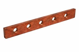
3. Copper Strip Terminal:
This terminal is the flat bar mounted at the top of the pit where the copper strip ends. It gives you a clear and stable point to connect the strip to the earthing system above ground. The terminal has multiple holes so you can bolt the strip securely and make future inspection or maintenance easy.
Its job is simple. Hold the strip in place, provide a firm mechanical support, and ensure a clean electrical connection between the buried earthing system and the equipment on the surface.
4. GI pipe:
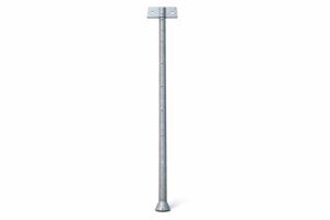
This GI pipe is perforated pipe for watering, as shown in the diagram. Its job is to carry water down to the soil around the copper plate, so the moisture level stays stable.
Moist soil keeps the resistance low and helps the fault current move into the ground quickly. The holes along the pipe allow the water to spread around the plate. The pipe is made of galvanised iron, so it can stay in the soil for long periods without corroding fast.
5. Funnel:
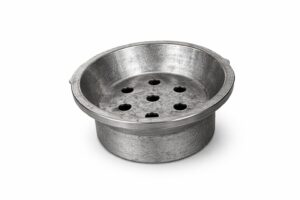
This funnel with mesh is placed at the top of the watering pipe. You pour water through this funnel to keep the soil around the plate moist. The mesh prevents stones, leaves, or debris from entering the pipe and blocking the flow of water. Using a funnel and mesh keeps the watering arrangement clean and accessible, so that moisture can reach the electrode effectively.
6. Now the U bolt:
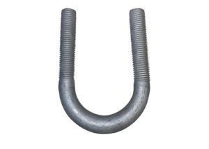
These bolts hold the plate earthing assembly in position and keep the copper strip aligned as it rises toward the terminal. Their job is mechanical, not electrical. They make sure the strip does not bend, twist, or shift inside the pit. A stable strip helps maintain a reliable path for fault current.
We hope you now have a brief idea about Plate Earthing Diagram. At Axis, we have a team of 50+ engineers who design, install, and test Earthing and Lightning Protection Systems as per your requirement.
Our products have been used in substations, data centres, factories, and even in everyday residential and commercial buildings. If you found this video helpful, please give it a like and subscribe to our channel for more insightful content on Electrical Engineering.
Thank you for reading and if you found this informative, then feel free to contact us to get a quote or to know more about our products; visit our product section at https://axis-india.com/products/ Follow us on LinkedIn for regular updates on our Products!