Follow us on LinkedIn for the latest updates
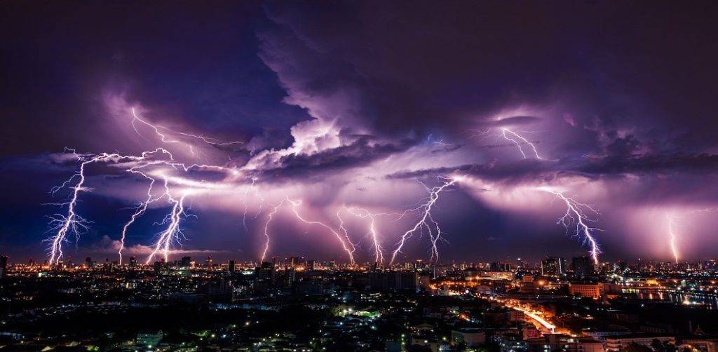
Most lightning never even reaches the ground, it just stays within the cloud where they originate. Sometimes a charge may escape the cloud and create a magnificent piece of art for photographers along with a loud boom for nearby observers. However, these beautiful natural phenomena that last for only a fraction of a second are immensely dangerous, killing people all over the world. Let’s focus on what lightning is & why lightning occurs?
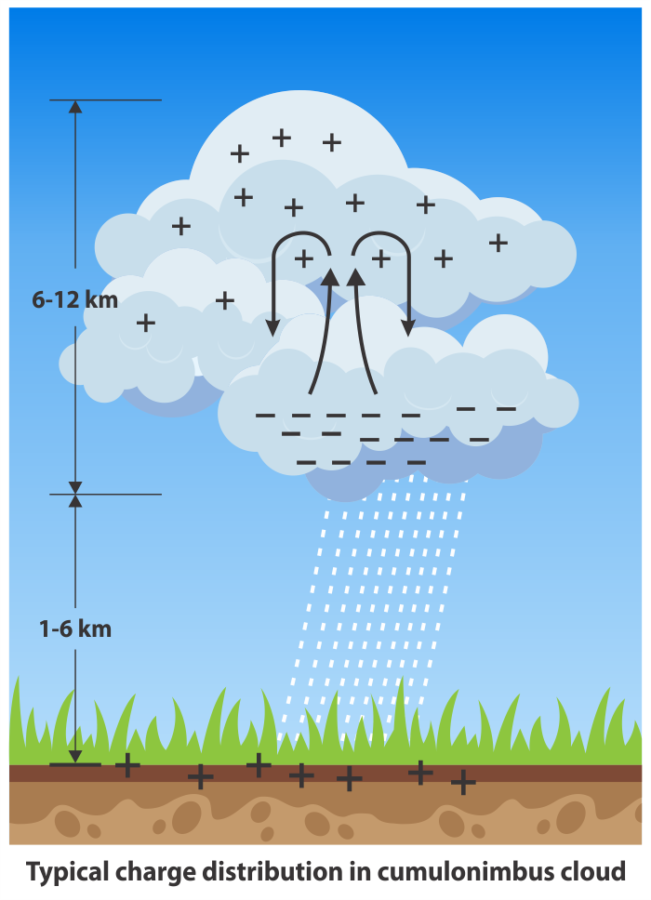
Thus, Lightning is a massive discharge of electricity over the atmosphere. The clouds that cause this discharge are usually 8 – 12 km long and are often nearly 2km away from the surface of the Earth with temperatures within these clouds in the range of -35 to -45° Celsius.
How does Lightning Form?
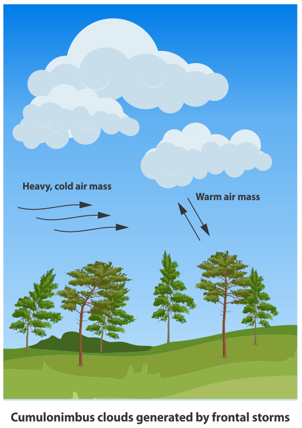
To put it simply, lightning is caused by the interaction of hot and cold air. The hot air which has been heated by the sun rises to meet cooler air columns in the upper atmosphere. This rising hot air carries water vapour along with it which condenses on meeting the cooler air – thus causing convective storm activity. This system of rising and cooling can become a self-sustaining process that can lead to large cumulonimbus clouds which can rise to more than 15,000 metres. Usually, the cloud needs to be about 3-4 km in height in order to be capable of generating lightning.
Convective currents are not the only method of creating lightning capable cumulonimbus clouds. Lightning can also be formed by the front of cold air that is moving towards an area of moist warm air. The difference in this scenario is that due to the movement of cold air, the clouds can extend over several kilometres in width.
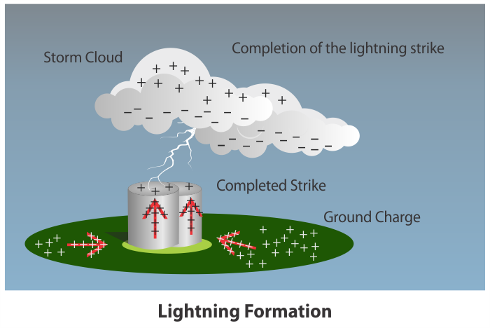
The momentum created by the movement of dust and ice particles creates static charges in the clouds. These static charges are responsible for charging the water droplets and ice particles in the cloud. As the clouds discharge their rain, the individual droplets carry the charge from the cloud to the earth, thus causing the cloud to develop features of a dipole where the top and bottom of the cloud carry opposite charges. Approximately 90% of all lightning is cloud to cloud and only about 10% of these escape the clouds to form cloud to ground lightning. For lightning protection, our focus is on those 10% of lightning strikes that hit the ground.
Why lightning occurs?
The separation of charges within the cloud causes the electrical potential to increase. This electrical potential keeps increasing to the point where a neutralising discharge must occur. For cloud to ground lightning, a leader initiates from the bottom of the cloud and starts its journey towards the ground. As this leader approaches the ground, the potential difference may be as high as 100 million volts. As a result, the ground discharge (upward leader) begins moving up, meeting the downward leader above the ground level – this could be anywhere between 10’s of metres to 100’s of metres above the ground. When this occurs, a low impedance path to the ground is created and the strike occurs.
Lightning strike parameters
- The lightning strike displays a quick rate of increase of current, typically around 10 kA/m
- The air around a lightning strike is heated up to 20,000 degrees C causing thunder.
- Lightning strikes to the ground can produce 100 million volts.
- The Peak current for lightning strikes is typically around 30kA.
Lightning Protection
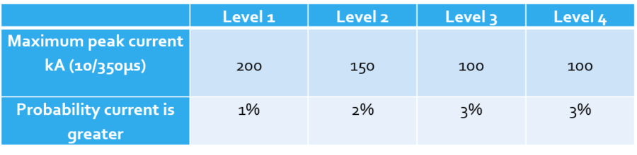
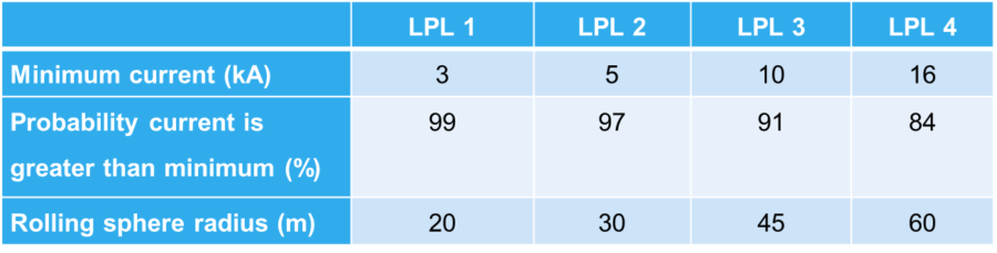
Lightning Protection systems for structures and buildings follow the international standard IEC 62305 for designs & calculation. As per the standard, there are four levels of protection that are shown in the table below. The standard uses statistical data on amperage and rate of rising of multiple types of lightning strokes to protect the structures against maximum and minimum values of currents. As seen in the table below, Level 1 has the highest level of protection with the probability of currently being greater at only 1% while level 4 has the lowest level of protection.
Types of Lightning Current Waves
Surges produced by lightning have a high magnitude but a short duration. Lightning discharge may reach its maximum value of approximately 1 to 20 microseconds & produce conduction flashover voltage 5 to 20 times in normal in one microseconds or less.
As per the IEC standard, there are 2 types of Current Waves to consider
Direct lightning strike 10/350 µs
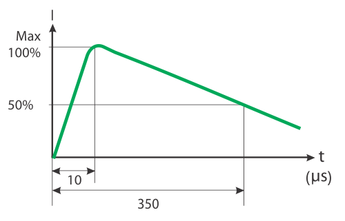
This characteristic is between maximum current versus time, in which 10 µs is the time to achieve the maximum value of current & 350 µs is the decay time of current to reach 50% of its maximum value.
Indirect Lightning Strike 8/20 µs
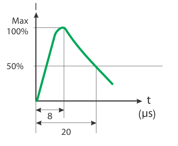
This characteristic is between maximum current versus time, in which 8 µs is the time to achieve the maximum value of current & 20 µs is the decay time of current to reach 50% of its maximum value.
Overvoltage created by the lightning, stroke is characterised by the 1.2/50 µs voltage
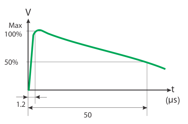
This characteristic is between maximum voltage versus time, in which 1.2 µs is the time to achieve maximum value of voltage & 50 µs is the decay time of current to reach 50% of its maximum value.
Striking Distance and Lightning Protection
When determining the placement of the air termination rods or other lightning protection, the main consideration is the minimum expected value of the current. “Striking Distance” is the distance that the upward leader travels to intercept with the downward leader. The striking distance is directly correlated with the charge carried by the leader which in turn is proportional to the lightning current. Hence, the striking distance (r) can be denoted by the following equation:
r=10 I^0.65
where I = peak current of the resulting stroke
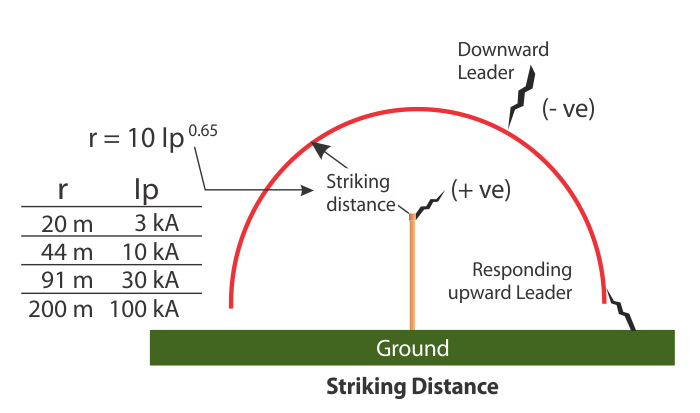
What we can clearly see from the formula above is that it is easier for smaller flashes to escape the lightning protection for a building. For example, if two air termination rods are placed 60m apart and a small flash with peak current of 3 kA occurs directly between them, neither air termination rod would be able to prevent the flash from damaging the structure or building. Therefore, to protect against smaller flashes, more air termination rods would be required for proper protection of the structure.
Using these theories, IEC 62305 defines 4 Levels of Protection against which a minimum current level is determined as seen in the table below. To continue our example above, if the Class of Protection for the building had been selected as Level I and the air termination rods had been placed accordingly, then 99% of all lightning flashes (of 3kA and above) would be intercepted by the air termination rods.
The striking distance formula directly connects to the most popular method of designing a lightning protection system – the rolling sphere method. Using the formula and the minimum currents chosen for each Level of Protection, we can determine the radius of protection for each air termination rod.
Rolling Sphere Method
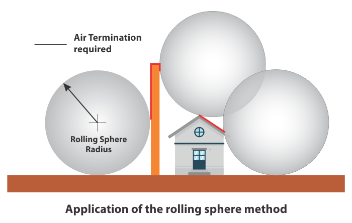
The Rolling Sphere Method is an aid to identify the areas of a building or structure that needs protection using air termination rods. This method also takes into account the possibilities of strikes to the side of the building. As illustrated below, a sphere, with radius defined by the Class of LPS, is rolled across a structure. Wherever the surface of the sphere comes into contact with the structure is deemed to be unprotected, thus requiring air termination.
Software to aid Lightning Protection Design
As you have read above, assessing, designing and finally constructing a safe and reliable Lightning Protection System is not an easy task. It requires many measurements, calculations, and experience to execute perfectly. In addition to the products and 25 years of experience that Axis offers, we also offer a software suite that will help simplify all your lightning protection calculations so that you can put your head towards providing the best service for your clients. Axis can also help you with the entire process from Step 1 of Risk Assessment to Lightning Protection System Design and all the way through the supply of internationally approved products. Our engineers will be on the field with you to make sure that they provide the most precise protection for your structure!

For more information on our Software Solutions or our Risk Assessment and System Design, please contact us!
This article is part of our series of articles on Lightning Protection, Surge Protection & Earthing, you can read more with the following links:
Surge Protection Devices (SPD)
Lightning Protection Zones and their Application to SPD Selection
How does a Lightning Arrester work?
For more information, please contact us at axis-india.com/contact-us/