In the world of electrical safety, earthing or grounding is a critical safety measure that protects both people and equipment. In this blog, you will understand the concept of “Structural Earthing,” a standard construction practice that offers numerous benefits. We’ll also compare it with “Conventional Earthing” another essential method in the field.
What is Structural Earthing?
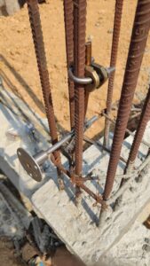
A metallic structure which has the current-carrying capability is likely to be hit by lightning or a fault current due to a fault occurring in the equipment attached to the structure. Hence the structure needs to be protected. The structure is required to have a low-impedance path to the grounding system to transfer the fault current safely into the ground within a second.
Structural Earthing is a technique that involves the use of a building’s natural components, such as metal reinforcements in ceilings, walls, and facades, to create a large-volume shield or a Faraday cage. This shield provides a path for lightning or fault currents, dispersing them through numerous parallel paths. This dispersion reduces the voltage drop due to the lightning current, ensuring the safety of the structure and its occupants.
Structural Earthing is primarily used for non-electrical equipment. It offers several advantages, including increased safety for humans during lightning strikes, protection for electrical installations during faults, and shielding for electronic systems against Electro Magnetic Pulse (EMP). Moreover, Structural Earthing systems are resistant to corrosion, require less maintenance, and are economical in the long run.
What is Conventional Earthing?
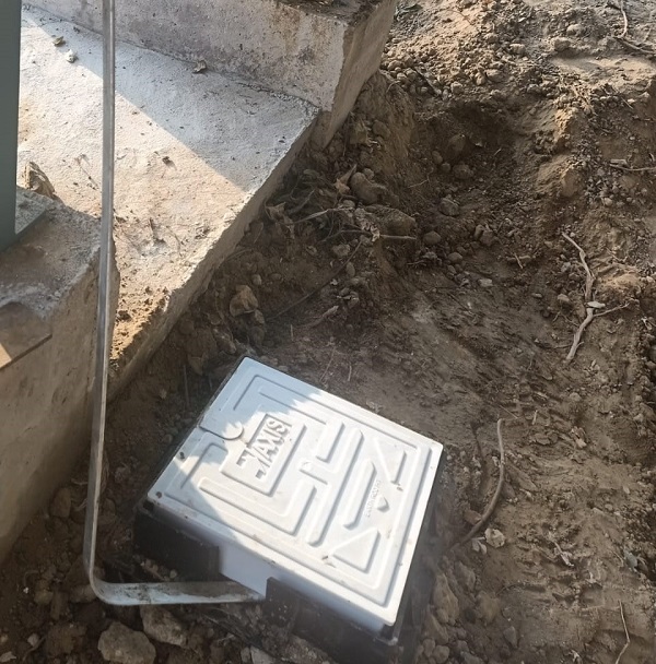
Conventional Earthing, on the other hand, is an independent system where a dedicated earthing conductor is connected directly between the electrical equipment or the metallic structure to the earth pit or a network of earth pits. The size of the earthing conductor depends on the magnitude of the fault current. This method is primarily used for electrical equipment.
Watch our video for more information on Conventional Earthing
Pros and Cons of Structural Earthing & Conventional Earthing
A) Structural Earthing
- Economical and does not involve dedicated earthing: Structural Earthing utilizes the existing metallic components of a structure (like the metal reinforcements in ceilings, walls, and facades) to create a large-volume shield or Faraday cage. This eliminates the need for a separate, dedicated earthing system, making it a cost-effective solution.
- Easy Maintenance: Since Structural Earthing uses the building’s inherent components, it doesn’t require extensive upkeep. There’s no need for regular checks for corrosion, theft, or vandalism that you might find with a separate earthing system.
- Recommended only for non-electrical equipment: Structural Earthing is primarily used for non-electrical equipment and structures. It’s designed to protect the structure and its occupants from lightning strikes and faults.
- Good life span as it does not involve a complex network: The simplicity of Structural Earthing contributes to its longevity. Without a complex network of additional components, there are fewer elements that can fail over time.
- Not a superior conductor to carry the fault current: While Structural Earthing is effective for its intended purposes, it’s not the most efficient method for carrying large fault currents. This is where Conventional Earthing comes into play.
- No additional area or space is required: Since Structural Earthing uses the existing structure, it doesn’t require any extra space. This can be a significant advantage in areas where space is at a premium.
B) Conventional Earthing
- Meant to ground the electrical equipment: Conventional Earthing is designed specifically to ground electrical equipment. It provides a direct, low-resistance path for electrical faults to flow to the ground, reducing the risk of electrical shock.
- Carries large fault current effectively to the ground: The dedicated earthing conductor in a Conventional Earthing system is sized to carry the full fault current safely to the ground. This ensures that electrical equipment is protected in the event of a fault.
- Provides utmost safety to human lives: By effectively grounding electrical equipment and carrying fault currents away, Conventional Earthing significantly reduces the risk of electrical shock, providing a high level of safety for individuals.
- Requires more effort to maintain: Unlike Structural Earthing, Conventional Earthing involves a separate system that requires regular maintenance. This includes checking for and addressing issues like corrosion, as well as ensuring the system remains effective at grounding electrical equipment.
- More area of space is required: A Conventional Earthing system requires space for the installation of the earthing conductor and earth pits. This can be a consideration in areas where space is limited.
Structural Earthing Vs Conventional Earthing
The main purpose of Earthing or Grounding is to provide a reliable return path for any fault current that may be developed during a short circuit between phases or phase to ground. Please refer to the below figure, in which the electrical power is generated by the Generator.
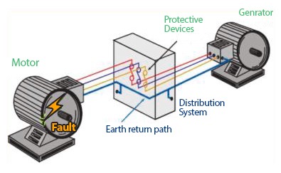
Let’s assume there is a fault within the motor i.e phase to phase or 3-phase fault. In such a case, the fault current is returned to its source and not to ground if the system is not grounded. Under normal circumstances, a fault at the motor should cause sufficient current to flow for operating the protective devices. Devices such as circuit breakers or fuses are located in the distribution system in a short time based on the characteristics curves and settings provided (in the case of Circuit Breakers) to trip and isolate the fault.
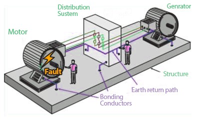
Hence the earth’s return path (shown in blue colour cable in the above diagram) has to be grounded through cable/conductors at least two points (for redundancy) to the earth grid in which the earth pits are connected. This is the conventional way of earthing the electrical system.
Structural earthing is the method by which the nearby conducting materials are interconnected together. Please refer to the below figure.
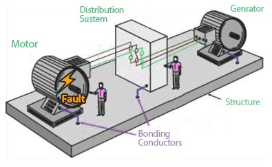
Structural earthing provides a path for structural currents and ensures that the interconnected equipment is at the same potential. The above figure shows that the equipment such as Generator, Power Distribution Board and Generator bodies are connected to the structure (metallic skid) and hence no potential difference exists that threatens personnel safety. The equipment earthing is effectively in parallel with the human and the fault current is divided between them.
Conclusion
Structural Earthing and Conventional Earthing are required to be used based on the application and the magnitude of the fault current.
Please refer to the figure. When both conventional earthing and structural are complete for the above-considered example, then they will add value to one another.
The Structural Earthing provides an alternative return path, and the earthing conductor duplicates the function of the structural earthing.

This article is part of our series of articles on Lightning Protection, Surge Protection & Earthing, you can read more with the following links:
Surge Protection Devices (SPD)
Lightning Protection Zones and their Application to SPD Selection
How does a Lightning Arrester work?
Thank you for reading the blog, Axis is a leading manufacturer and supplier of Electrical Components to over 80+ Countries. Talk to our industry expert by visiting our contact us section. You can also watch our videos by our experts – click here.