Follow us on LinkedIn for the latest updates
The protective angle method is one of the three routes for lightning protection system design defined by IEC 62305, the international standard for lightning protection design. After the first step of determining the class of lightning protection decided by the Risk Assessment, the lightning protection system design can be done using the Rolling Sphere, Protection Angle method or the Mesh method. The system design will provide information such as location of the lightning arresters, down conductors, earth electrodes, other equipment and the complete Bill of Material.
Protective Angle Method
The protective angle method is best used on simple structures. Additionally, the Protective Angle Method is only valid up to heights equal to the radius of the rolling sphere as defined by the class of LPS defined for the structure. For structures with a protruding metallic structure, the Protective Angle Method is generally used as a supplement to the Mesh Method.
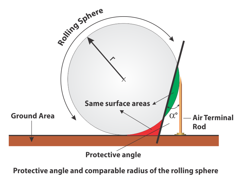
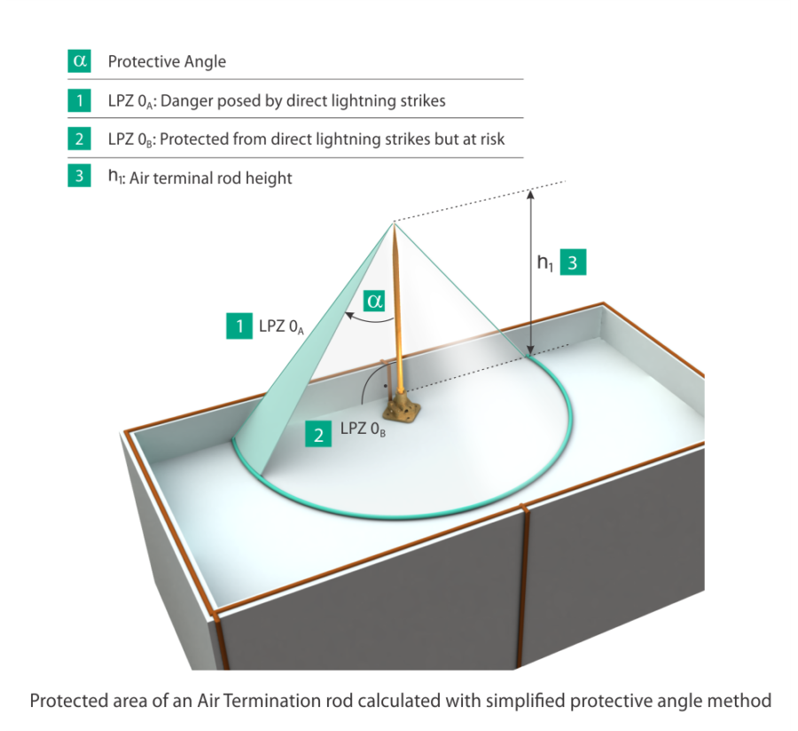
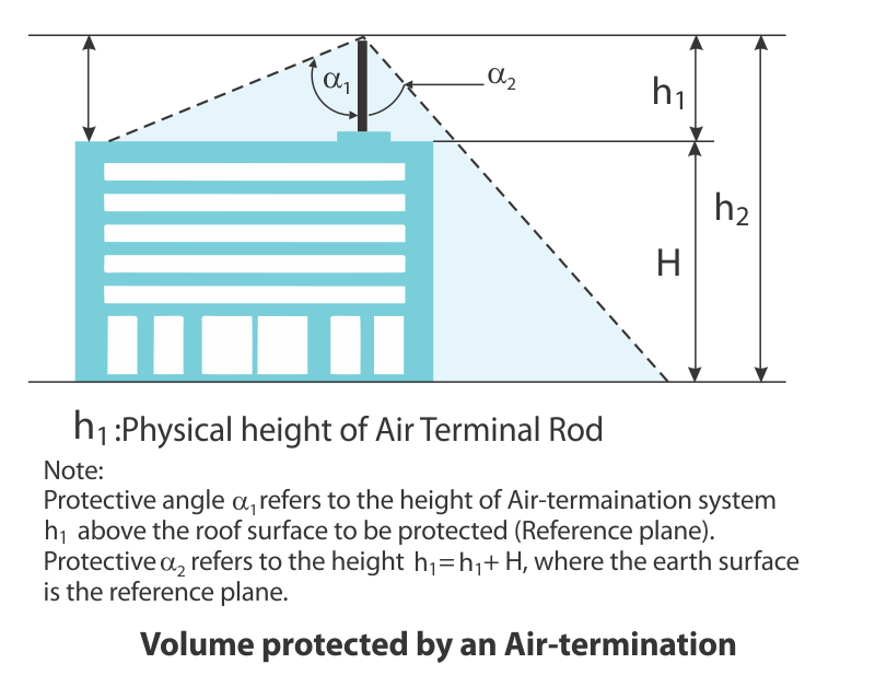
The protective angle method is commonly referred to as a mathematical simplification of the rolling sphere method. The protective angle is determined in such a way that when the slope intersects the rolling sphere, the additional area under the protective angle (marked green in the figure below) and the area that is now not under the protective angle (marked red in the figure below) are equal.
How does the Protective Angle work?
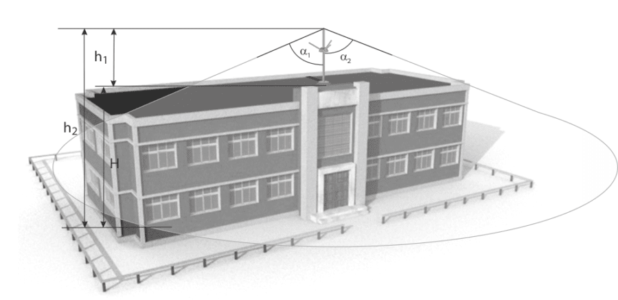
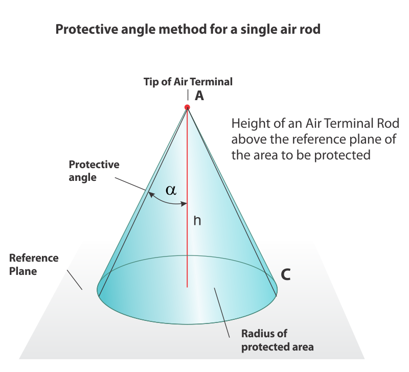
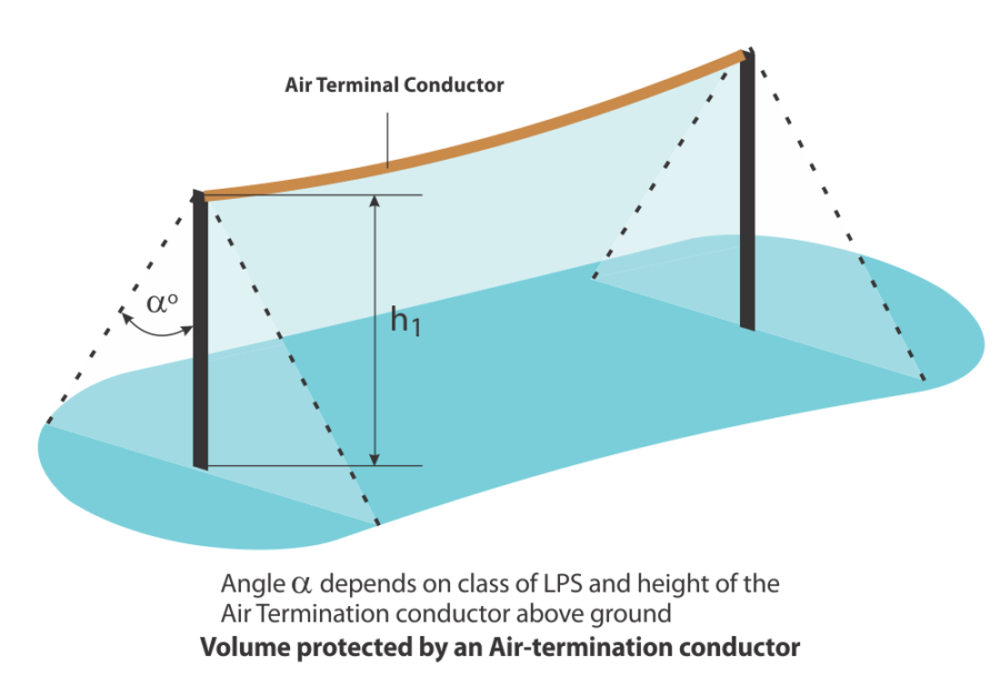
The protective angle method is a 3D concept as shown in the figure below. The protected area is the cone that is swept by the line that emerges from the tip of the air termination rod and ends at the surface of the structure. The protected area will be cone-shaped in the case of a simple air termination rod but it can also be a tent-shaped protected area in case of a catenary wire as shown in the figure below.
So what Protective Angle should I use?
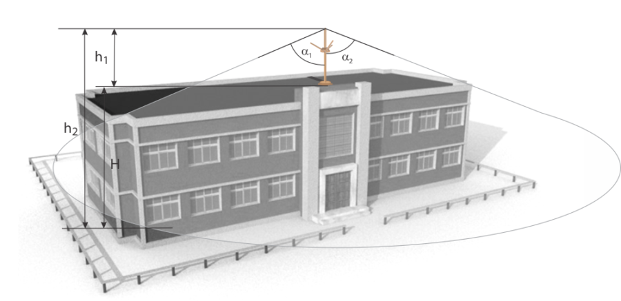
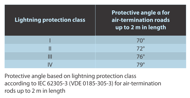
The protective angle (a) depends on the Class of LPS and the height of the air rod. The angle is determined from Table 2 from IEC 62305-3. For simplicity’s sake, the table below shows the protective angle for air termination rods that are up to 2m in length.
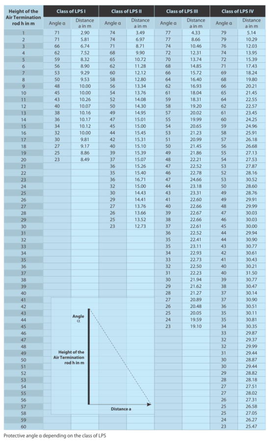
The table below is a more comprehensive guide for different heights of the air termination rod and the corresponding protective angles (a).
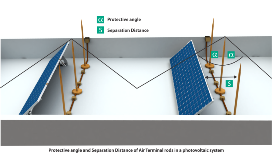
Protective Angle Method to Protect Rooftop Solar from Lightning
With the advent of rooftop solar across India and the world, protecting this expensive and sensitive equipment is a priority. As shown in the figure below, we can easily protect our PV modules and equipment by using the protective angle method. Please note that we should ensure enough separation distance between the PV modules and the Air Termination Rods in order to prevent sparking.
Software to aid Lightning Protection Design
As you have read above, assessing, designing and finally constructing a safe and reliable Lightning Protection System is not an easy task. It requires many measurements, calculations, and experience to execute perfectly. In addition to the products and 25 years of experience that Axis offers, we also offer a software suite which will help simplify all your lightning protection calculations so that you can put your head towards providing the best service for your clients. Axis can also help you with the entire process from Step 1 of Risk Assessment to Lightning Protection System Design and all the way through the supply of internationally approved products. Our engineers will be on the field with you to make sure that they provide the most precise protection for your structure!
For more information on our Software Solutions or our Risk Assessment and System Design, please contact us!
This article is part of our series of articles on Lightning Protection, Surge Protection & Earthing, you can read more with the following links:
Surge Protection Devices (SPD)
Lightning Protection Zones and their Application to SPD Selection
How does a Lightning Arrester work?
For more information, please contact us at www.staging.axis-india.com/contact-us/