In this article, we will explore the importance, design & installation of Lightning & Surge Protection for wind turbines. This essential topic explores the cutting-edge strategies and technologies used to protect these towering giants from lightning strikes and transient over-voltages, ensuring their reliable operation, minimising downtime, and safeguarding valuable components in today’s rapidly expanding renewable energy landscape.
Wind Turbines are particularly susceptible to lightning strikes and the subsequent damage. Lightning and Surge protection is essential for wind turbines because of their:
- Vulnerability to Lightning Strikes: Wind turbines are often situated in exposed locations and have significant height, making them prime targets for direct lightning strikes. On average, multi-megawatt wind turbines can experience at least 10 direct strikes annually.
- High Investment Costs and Downtime: Wind turbines require substantial initial investments, and the generated electricity must be fed into the grid to recoup these costs within a few years. Downtime caused by lightning or surge damage can result in expensive repair costs and hinder the return on investment. Thus, comprehensive protection measures are necessary to minimise downtime and protect the asset.
- Upward Leaders: In addition to the more common cloud-to-earth lightning strikes, wind turbines with a height exceeding 60 meters may also experience upward leaders, or earth-to-cloud flashes. These tend to occur primarily during winter months and can carry charges higher than 300 Coulombs (C), necessitating robust protection measures.
- High charges and system damage: High charges associated with lightning strikes, especially upward leaders, can lead to significant damage to wind turbine components. For example, charges during winter storms can cause melting of conductor systems, spark gaps, and other essential parts. Consequently, it is crucial to design protection systems with higher requirements to withstand these extreme conditions.
International Standards

IEC 61400-24 specifically addresses lightning protection for wind turbine generators, providing guidelines for design, testing, and assessment to minimise potential damage from lightning strikes.
IEC 62305 is a broader standard that covers general lightning protection for structures and electrical systems, including risk assessment, protection measures, and installation requirements.
Lightning Protection System Design
Deciding the lightning protection level and lightning protection zones (LPZs) for wind turbines involves considering factors such as the turbine’s location, its size, and the specific characteristics of its electrical and electronic systems. IEC 61400-24 and IEC 62305-3, provide guidelines for determining these parameters.
Lightning Protection Levels (LPL)
The lightning protection level is determined based on the expected lightning threat to the wind turbine. LPLs are classified into four levels, from LPL I (highest protection) to LPL IV (lowest protection). The selection of the LPL depends on the wind turbine’s exposure to lightning, its importance to the overall power grid, and the potential consequences of a lightning strike (e.g., downtime, repair costs, and safety hazards).
Higher LPLs entail more robust protection measures, which may include additional air termination systems, down conductors, and earth termination systems.
The IEC 61400-24 standard recommends protecting all sub-components of the lightning protection system of a wind turbine according to LPL I (highest protection) unless a risk analysis demonstrates that a lower LPL is sufficient. A risk analysis may also reveal that different sub-components have different LPLs.
Lightning Protection Zones (LPZs)
The concept of LPZs is used to define the boundaries within which specific lightning protection measures are required. Wind turbines typically have three LPZs:
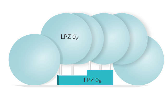
- LPZ 0A: This zone is directly exposed to lightning strikes and is characterised by the presence of the air termination system, including receptors on blades, the nacelle, and the tower. The electromagnetic fields and lightning currents in this zone are the highest. The air termination system is designed to capture and safely direct the lightning energy to the earth termination system. All external structures and systems within this zone need to be able to withstand the direct effects of a lightning strike.
- LPZ 0B: This zone is not directly exposed to lightning strikes but is subject to partial lightning currents due to the electromagnetic fields created by a nearby lightning event. Components and systems within this zone, such as the tower base, cables, and control systems, need protection against both induced and conducted surges. Surge protection devices (SPDs), such as type 1 lightning current arresters, are typically installed at the boundary between LPZ 0A and LPZ 1 to protect against high-energy surges.
- LPZ 1 and higher: These zones are located within the wind turbine, including the nacelle, hub, and control room, where the electrical and electronic equipment is housed. These zones are protected by the measures implemented in the outer zones, and their primary concern is the protection against indirect lightning effects. SPDs, such as type 2 and type 3 surge arresters, are installed at the boundaries between these zones to further reduce the residual interference from the outer zones and to limit the surges induced within the wind turbine.
Location of Transformer, Switchgear, and Control Cabinets
The locations of the wind turbine’s transformer, medium-voltage switchgear, and control cabinets play a significant role in the design of the lightning protection system. Each component’s placement influences the routing of cables and conductors, the selection of surge protective devices (SPDs), and the overall coordination of the protection system. Here are some ways these locations can affect the lightning protection design:
Proximity to Vulnerable Components: The closer these components are to the wind turbine’s vulnerable areas, such as the hub or nacelle, the higher the risk of lightning-induced damage. Proper shielding and isolation measures must be taken to protect these components from direct and indirect lightning strikes.
Cable Routing: The transformer, medium-voltage switchgear, and control cabinets are connected through various cables, and their placement affects the cable routing. Cable routes should be designed to minimise exposure to lightning-related electromagnetic fields and potential surges, ensuring proper shielding and grounding.
Lightning Protection Zones: Each component’s location influences the division of the wind turbine into different LPZs. Each zone has specific requirements for the installation of surge protective devices (SPDs) to safeguard sensitive equipment. Properly defining and implementing LPZs is crucial for an effective lightning protection system.
Electromagnetic Interference (EMI): The proximity of these components to each other and to the lightning protection system can result in electromagnetic interference, which can potentially cause malfunctions or damage to sensitive equipment. Lightning protection design must consider EMI and take measures to mitigate its effects, such as shielding or proper grounding.
Thermal effects: The heat generated by the transformer and medium-voltage switchgear can influence the performance of the lightning protection system components, such as SPDs and conductors. Proper ventilation and thermal management should be considered in the design to ensure the components function optimally and avoid overheating.
Aircraft Warning Light: The aircraft warning light should be integrated into the wind turbine’s air termination & main grounding system to prevent direct lightning strikes on the light and associated damages. Proper shielding techniques, such as shielded cables or enclosing cables in grounded metallic conduits, are also necessary to protect the aircraft warning light’s control and power cables from EMI caused by lightning events.
Main Components of a Wind Turbine Lightning Protection System
Risk Assessment: A thorough risk assessment must be conducted to identify and evaluate the potential hazards posed by lightning strikes. This assessment helps determine the necessary protection level for the wind turbine, which guides the overall design of the lightning protection system.
Air Termination System: This includes lightning rods, receptors, or air termination devices installed on the wind turbine’s blades, nacelle, and hub to intercept direct lightning strikes. The air termination system ensures that the lightning energy is safely directed to the down conductors.
Down Conductors: These are conductive paths that safely guide the lightning current from the air termination system down to the earth termination system. Down conductors should be made of corrosion-resistant materials and be installed to minimise inductive loops.
Earth Termination System: This system consists of earth electrodes, such as ring earth electrodes and foundation earth electrodes, which safely dissipate the lightning current into the ground. The earth termination system plays a crucial role in maintaining safety and minimising step and touch voltages during a lightning strike.
Equipotential Bonding: This involves interconnecting all metallic structures, conductive systems, and equipment within the wind turbine to create a consistent potential distribution. Equipotential bonding minimises voltage differences during a lightning strike, reducing the risk of flashovers and equipment damage.
Surge Protective Devices (SPDs): SPDs are installed at the point of entry of power lines, control and signal cables, and telecommunication lines to limit voltage surges and protect sensitive equipment from damage. Proper selection and installation of SPDs are essential to ensure effective protection.

Air Termination System for Wind Turbines
The air termination system is a crucial part of a wind turbine’s lightning protection system. Its primary function is to intercept direct lightning strikes and safely direct the lightning current towards the down conductors and earth termination system. An effective air termination system helps minimise the risk of structural damage, equipment failure, and fire hazards.
Designing an effective air termination system for wind turbines requires a thorough understanding of the lightning protection standards, such as IEC 61400-24 and IEC 62305-3, as well as the specific characteristics of the wind turbine, including its size, location, and structural features.
For wind turbines, the air termination system comprises several components including:
-
- Blade Receptors
- Nacelle Receptors
- Hub Receptors
- Lightning Rods
- Conductive Paths
- Interconnection
Blade Receptors: These are installed on the wind turbine blades to capture lightning strikes that hit the blades. They are typically made of conductive materials like copper or aluminium, and their placement and number depend on the blade’s length, material, and shape. Blade receptors can be installed on the blade’s leading edge, trailing edge, or tip, depending on the specific design requirements.
Nacelle Receptors: Nacelle receptors are installed on the nacelle’s outer surface to protect it from direct lightning strikes. These receptors are typically placed at strategic locations on the nacelle, such as the corners or other exposed points. In some designs, a lightning rod may be installed on top of the nacelle to provide additional protection.
Hub Receptors: Hub receptors protect the hub from direct lightning strikes by capturing and directing the lightning current towards the down conductors. They are typically installed at the highest points of the hub or at other locations where lightning is most likely to strike. Hub receptors can be made of conductive materials like copper or aluminium and are strategically placed to ensure maximum protection.
Lightning Rods: In addition to nacelle receptors, lightning rods may be installed on top of the nacelle or at other vulnerable points of the wind turbine structure. These rods extend vertically upward and act as preferential strike points for lightning, further increasing the effectiveness of the air termination system.
Conductive Paths: To ensure that the intercepted lightning current is safely directed from the receptors to the down conductors, conductive paths must be established. This involves connecting the blade, nacelle, and hub receptors to the down conductors using conductive cables or metallic strips. These paths should have low resistance and inductance to minimise voltage drops and electromagnetic interference.
Interconnection: Proper interconnection of all the components of the air termination system is vital for ensuring its effectiveness. This includes connecting the receptors to the down conductors and maintaining electrical continuity throughout the entire system. The connections should be secure and corrosion-resistant to ensure long-term reliability.
Down Conductor System
The down conductor system is a crucial component of a wind turbine’s lightning protection system. Its primary function is to safely conduct lightning currents from the air termination system to the earth termination system, minimising the risk of damage to the wind turbine’s structure and internal systems.
Here are the main features of a well-designed down conductor system for wind turbines:
- Material: Down conductors should be made of highly conductive and corrosion-resistant materials, such as copper or aluminium. The selection of the material depends on factors like compatibility with other metallic components, environmental conditions, and cost.
- Cross-sectional area: The cross-sectional area of the down conductors should be sufficient to handle the lightning currents without causing excessive heating or mechanical stress. The IEC 62305-3 standard provides recommendations for minimum cross-sectional areas based on the selected lightning protection level (LPL).
- Routing: Down conductors should be routed as straight and direct as possible from the air termination system to the earth termination system, minimising sharp bends and loops. This helps to reduce the inductance and impedance of the conductive path, ensuring efficient dissipation of lightning energy.
- Number of Down Conductors: Multiple down conductors may be required for larger wind turbines to provide an even distribution of lightning current and to reduce the risk of side flashes. The IEC 61400-24 standard recommends at least two down conductors for wind turbines with a hub height of up to 65 meters, and at least four down conductors for wind turbines with a hub height exceeding 65 meters. The exact number of down conductors depends on the turbine’s size, structure, and the selected LPL.
- Separation: Down conductors should be evenly distributed around the wind turbine’s structure to minimise the risk of side flashes and to ensure a balanced distribution of lightning current. They should also be separated from other conductive parts and internal systems to reduce the possibility of damage due to induced voltages and magnetic fields.
- Intermediate Supports: Depending on the length of the down conductors and the wind turbine’s structure, intermediate supports may be required to maintain proper tension and alignment. These supports should be made of insulating materials or electrically continuous with the down conductors to prevent the creation of a potential difference.
- Connections: The down conductors should be securely connected to the air termination system, the earth termination system, and any other metallic components requiring equipotential bonding. Connections should be made using corrosion-resistant and mechanically stable methods, such as exothermic welding or clamping.
- Inspection and Maintenance: Regular inspection and maintenance of the down conductor system are essential to ensure its continued effectiveness. This includes checking for corrosion, mechanical damage, and loose connections, as well as conducting periodic resistance measurements to verify the system’s performance.
Retrofitting Existing Wind Turbines
Retrofitting existing wind turbines with lightning and surge protection requires careful planning and consideration of several factors. Some specific considerations for retrofitting include:
- Compatibility with existing systems: The retrofit lightning and surge protection system must be compatible with the existing wind turbine’s electrical and structural components. This may require customizing the protection system to fit the specific turbine model and configuration.
- Minimising downtime: Retrofitting a lightning protection system can cause downtime for the wind turbine, which can affect the overall efficiency and productivity of the wind farm. Therefore, it is crucial to plan the retrofit process efficiently to minimise disruption and downtime.
- Structural modifications: Installing a lightning protection system may require structural modifications to the turbine, such as adding air termination rods or additional down conductors. These modifications must be carefully planned and executed to avoid compromising the structural integrity of the wind turbine.
- Accessibility: Accessibility to the wind turbine is essential when retrofitting a lightning protection system, especially for offshore wind turbines. Proper planning and coordination with maintenance crews, as well as ensuring the availability of necessary equipment, such as cranes or vessels, are crucial to ensure a smooth retrofit process.
- Compliance with standards: The retrofit lightning and surge protection system must comply with relevant standards, such as IEC 61400-24 and IEC 62305-3. It is essential to thoroughly review these standards and ensure that the retrofit protection system adheres to the requirements.
- Coordination with turbine manufacturers: Retrofitting a wind turbine with a lightning protection system may require close coordination with the turbine manufacturer to ensure the proper implementation of the system. This may involve obtaining technical support, guidance, and access to proprietary documentation.
- Cost-effectiveness: The cost of retrofitting existing wind turbines with lightning and surge protection should be weighed against the potential benefits, such as reduced downtime, lower maintenance costs, and increased turbine reliability. The investment in retrofitting should be justified by the expected long-term returns.
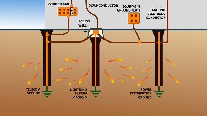
Earth Termination System for Wind Turbines
The earth termination system for wind turbines is a crucial component in ensuring the protection of the structure, its components, and the safety of individuals and animals in the vicinity. It serves multiple purposes, including personal protection, EMC protection, and lightning protection. To achieve these objectives, the earth termination system must adhere to the guidelines specified in the IEC 62305-3 and IEC 61400-24 standards.
Wind turbines are vulnerable to lightning strikes due to their height and metal structures, which make them attractive to lightning. When struck, the lightning current must be safely discharged to the ground and distributed without causing hazardous thermal or electrodynamic effects. Moreover, the earth termination system must protect people and animals against electric shock in the event of a lightning strike.
Arrangement of Earth Electrodes: The IEC 62305-3 standard describes two basic types of earth electrode arrangements for wind turbines: Type A and Type B.
Type A arrangements consist of horizontal or vertical earth electrodes connected to the building by at least two down conductors. According to Annex I of IEC 61400-24, Type A arrangements cannot be used for wind turbines themselves, but they can be employed for adjoining buildings such as those containing measurement equipment or office sheds for the wind farm.
Type B earth electrode arrangements are required for wind turbines, as stated in Annex I of IEC 61400-24. They consist of either a buried external ring earth electrode and/or a foundation earth electrode. Ring earth electrodes and metal parts in the foundation must be connected to the tower construction. To create an effective earth-termination system covering a large area, the tower base and operations building should be connected through a meshed earth electrode network. Corrosion-resistant ring earth electrodes, made of stainless steel (e.g., AISI / ASTM 316 Ti), with potential control are essential for preventing excessive step voltages during a lightning strike, ensuring personal protection. These electrodes should be installed around the tower base.
Foundation Earth Electrodes: Foundation earth electrodes are both technically and economically advantageous. As part of the electrical installation, they fulfil essential safety functions and must be installed by or under the supervision of a qualified technician. The metals used for earth electrodes must comply with the materials listed in Table 7 of IEC 62305-3. It is crucial to monitor the corrosion behaviour of metal in the ground at all times.
Typically, foundation earth electrodes are made of galvanised or non-galvanised (round or strip) steel. Round steel must have a minimum diameter of 10 mm, while strip steel must have minimum dimensions of 30 mm x 3.5 mm. This material must be covered with a concrete layer at least 5 cm thick for corrosion protection. The foundation earth electrode must be connected to the main earthing busbar in the wind turbine. Corrosion-resistant connections must be established via fixed earthing terminals or terminal clamps. The connections should be made using exothermic welding or mechanical clamps. Exothermic welding offers the advantages of creating a permanent, low-resistance connection that is highly resistant to corrosion, while mechanical clamps provide a simple and fast installation process. It is crucial to ensure that the connection points are well-protected from external influences, including moisture and corrosive substances.
To maintain an effective earth termination system, regular inspections and maintenance must be performed. The inspections should include measuring the earth electrode resistance and visually inspecting the connections for signs of corrosion or damage. The resistance measurement should be conducted using the fall-of-potential method or other appropriate techniques, as recommended by IEC 62305-3.

Equipotential Bonding
Lightning equipotential bonding is another critical aspect of an earth termination system. Equipotential bonding involves interconnecting all metallic structures, conductive systems, and equipment within the wind turbine to create a consistent potential distribution. This bonding ensures that any voltage differences are minimised during a lightning strike, preventing dangerous flashovers and reducing the risk of equipment damage. IEC 62305-3 provides guidelines for the design and installation of lightning equipotential bonding in wind turbines.
Here are the key guidelines for designing and installing lightning equipotential bonding in wind turbines as per IEC 62305-3:
1) Interconnecting all metallic parts: All metallic parts within the wind turbine, including the tower, nacelle, hub, and other internal components, must be interconnected. This is achieved using equipotential bonding conductors, which are designed to handle lightning currents.
2) Bonding conductive systems: Lightning equipotential bonding should encompass all conductive systems within the wind turbine, such as power supply lines, control and signal cables, and telecommunication lines. Equipotential bonding must also include metallic services like water pipes and ventilation ducts.
3) Use of surge protective devices (SPDs): SPDs should be installed at the point of entry of power lines and other conductive systems to minimise the risk of lightning surges entering the wind turbine. These devices help to limit voltage differences and protect sensitive equipment.
4) Equipotential bonding bars: The installation of equipotential bonding bars at strategic locations within the wind turbine is recommended. These bars serve as central connection points for bonding conductors and equipotential bonding cables.
I hope you now have a clear understanding of Earthing System. At Axis, we manufacture and supply a wide range of Earthing Materials, including Earth Rods, Earth Plates, Strips, Clamps, Earth Pits, and other accessories. We also help design complete systems for your structure, suitable for Substations Earthing, Solar Earthing, and residential or commercial structures.
Thank you for reading the blog, Axis is a leading manufacturer and supplier of Electrical Components to over 80+ Countries. To get a quote or to talk to our industry expert visit our contact us section. You can also watch our videos by our experts – click here.