Scope
Over the last century, electrical safety standards have evolved into very sophisticated systems that encompass all components of a safe installation, including TT Earthing Systems and other types in the category. In Low-voltage (LV) Electrical Installations, the reference standard IEC 60364 is used to determine the actions to ensure the safety of employees and property.
Introduction
The IEC 60364 standard divides the Earthing Systems into three categories: TT, IT, and TN. IEC develops International Standards for all electrical, electronic, and associated technologies and is the leading international organisation in its field. IEC 60364 is the apex level publication that informs the standards for LV Electrical Installations.

As a result, several national standards recognise IEC 60364’s three types of earthing systems. The IEEE Wiring Regulations 17th Edition, also known as British Standard BS 7671: 2008, was published in January 2008 and is used in the UK and other countries.
Indian Standard IS 732:1989 governs electrical installations in India (R2015), following IEC 60364.
| Public Distribution Example Worldwide (LV Consumers) – LV Earthing System | |||
| Sr. No. | Country | Voltage | LV Earthing System |
| 1 | India | 230/415 | TN-S |
| 2 | Germany | 230/400 | TT & TN-C |
| 3 | Belgium | 230/400 | TT |
| 4 | Spain | 240/400 | TT |
| 5 | France | 240/415 | TT |
| 6 | Great Britain | 240/415 | TT & TN-C |
| 7 | Italy | 230/400 | TT |
| 8 | Japan | 100/200 | TT |
| 9 | Norway | 230/400 | IT |
| 10 | Portugal | 230/400 | T |
| 11 | USA | 120/240 | TN-C-S |
What is TT Earthing?
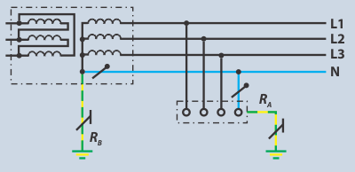
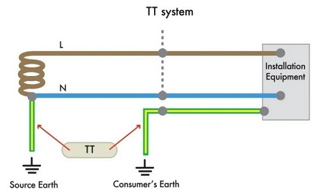
In this sort of Earthing System, the connection to the supply source is connected directly to the earth, and the load end or installation metalwork is also directly connected. As a result, in the case of an overhead line, the earth’s mass will serve as the line’s return path.
Because the power distributor only offers the supply neutral or protective conductor for the connection to the consumer, the neutral and earthing conductors must be separated during the installation.
First: T stands for Direct connection to the Earth & Second: T stands for Terra meaning Earth
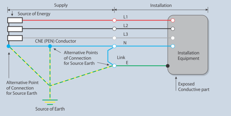
Significance of TT Earthing System and its graphical representation
This system is set up similarly to the TN-S system, except it does not provide users with their earth connection. The main objective is to reduce the earth resistance or provide low resistance (impedance) path.
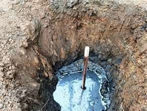
A consumer must insert dirt (wet mud or wet dust for better earthing) along with an earth electrode or earth plate for better earthing.
When TN-C-S setups aren’t possible (in the gas station example) or rural regions (where overhead poles provide power), TT systems are used. In places where diverse soil types may create an external fault loop, impedance values exist. Shock protection techniques such as RCDs provide immediate supply cut-off.
![]()
TT earthing main characteristics:
–It gets power from the public LV distribution network directly.
-No continual monitoring is required (a periodic check on the RCDs may be necessary).
-Special devices, known as residual current devices (RCDs), provide protection and reduce the chance of fire when set to less than 500 mA.
-Each insulation fault causes a power outage, but the outage is limited to the faulty circuit by connecting the RCDs in series (selected RCDs) or in parallel (parallel RCDs) (circuit selection).
-Loads or sections of the installation that create large leakage currents during operation require additional precautions to avoid nuisance tripping, such as supplying the loads with a separation transformer or using appropriate RCDs.
Comparison of various earthing systems:
| Sr. No. | TT | IT | TN-S | TN-C | TN-C-S |
| Earth Fault Loop Impedance | High | Highest | Low | Low | Low |
| RCD Preferred? | Yes | NA | Optional | No | Optional |
| Need earth electrode at site? | Yes | Yes | No | No | Optional |
| PE Conductor cost | Low | Low | Highest | Least | High |
| Risk of broken neutral | No | No | High | Highest | High |
| Safety | Safe | Less safe | Safest | Least safe | Safe |
| Electromagnetic Interference | Least | Least | Low | High | Low |
| Risks of safety | High loop impedance | Double fault | Broken Neutral | Broken neutral | Broken neutral |
| Advantages | Safe & Reliable | Continuity of operation | Safest | Cost | Safety & Cost |
Importance of RCD in TT Earthing System:
-All exposed-conductive portions of the installation/loads must connect to a common earth electrode in a TT earthing system.
-The source system’s neutral point is earthed outside the influence area via the ground electrode.
-As a result, the earth fault impedance consists primarily of two earth electrodes in series (i.e., the source and installation electrodes). The magnitude of the earth fault current is generally too small to operate overcurrent relays or fuses, necessitating a residual current operated device as first-level isolation.
-A TT system’s automatic disconnection is done by an RCD, with a sensitivity of IΔn ≤ 50\Ra (where RA is the resistance of the installation earth electrode).
-IΔn is the RCD’s rated residual operating current.
-The earth electrode’s resistance for the installation is RA.
-The value of 50 V is substituted by 25 V for temporary supply (to work sites, etc.) and agricultural and horticultural premises.
Source - scirp.org
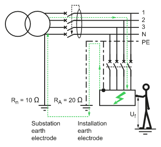
-The earth electrode of the substation neutral Rn has a resistance of 10 ohms.
-The earth electrode of the installation RA has a resistance of 20.
-Id = 7.7 A is the earth-fault loop current.
-The fault voltage Uf = Id x RA = 154 V, which is serious, but in 50/20 = 2.5 A, which means that a 300 mA RCD will clear the fault in roughly 30ms without intentional time delay if a fault voltage exceeding occurs on an exposed-conductive-part.
-The RCD will close the circuit if there is a leakage current in the system. By detecting tiny leakage currents, RCD’s may turn away electrocution as part of the automatic disconnection of power, which switches off when a fault develops in the circuit rather than requiring human intervention.
TT Earthing AC Power Supply System:
The grounding protection can considerably reduce the risk of electric shock when the metal shell of the equipment is charged (the phase line hits the shell or the equipment insulation is damaged and leaks).
Low-voltage circuit breakers (automatic switches) do not always trip, leading the earth-leakage voltage to exceed the acceptable voltage, making the voltage harmful.
A fuse may not explode when the leakage current is minimal. A leakage protector is mandatory for safety in such cases. As a result, popularising the TT system is challenging.
TT earthing system uses an ample amount of steel, recycling that steel is time-consuming and problematic.
Construction companies use TT. A unique protection line reduces the quantity of steel used for the grounding mechanism when the construction unit borrows its power supply for temporary energy use.
Separate the new special protection line PE from the working zero-line N, which has the following characteristics:
1) The grounding line and the working neutral line have no electrical connection.
2) The (working) zero lines can have current in operation, but the protection line can’t.
3) The TT system is well suited to areas where ground protection is sparse.
Applications:
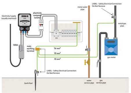
Remote areas use TT, where the cost of an additional PE conductor outweighs that of a local earth connection. Especially in older properties, where safety might otherwise be at risk by the fracture of an overhead PE conductor by, say, a fallen tree branch. In most TN-C-S systems, TT supplies to individual homes when a property is deemed unfit for TN-C-S service.
Installations on a construction site, a farm, or a swimming pool may be improper unless additional measures, like installing extra earth electrode is adopted.
For LV system earth, TT earthing helps in earthing such devices when low voltage arises in the system.
All metallic enclosures and extraneous parts are at equipotential.
Protection from lightning because of low fault current.
Protection from earth fault current because of low resistance path.
Advantages of TT Earthing:
-Simplicity (very few calculations when installing)
-Extension that does not necessitate the calculation of lengths
-Fault currents are low
-There is very minimal upkeep
-Operation with a low projected current source
-Ease of entry for conductors, smooth edges
-It is economical, safe and high graded in use
-Good withstanding capacity against harmonics supplied in the system
Conclusion
The TT Earthing System is one of the most reliable and widely used grounding methods for installations where a direct connection to the supply earth is not feasible. It offers enhanced electrical safety by isolating the consumer’s earthing from the utility’s network, minimizing the risk of electric shock and equipment damage. When combined with RCD protection, it ensures rapid fault disconnection and compliance with international standards such as IEC 60364 and IS 732. Proper design, installation, and periodic testing of TT earthing systems are vital for maintaining safe, efficient, and long-lasting electrical installations.

Thank you for reading the blog, Axis is a leading manufacturer and supplier of Electrical Components to over 80+ Countries. Talk to our industry expert by visiting our contact us section. You can also watch our videos by our experts – click here.
Follow us on LinkedIn for regular updates on our Products!

FAQ
Q1. What is a TT earthing system and how does it work?
A: A TT earthing system is a type of grounding system where both the power supply neutral and the consumer’s installation are directly connected to separate earth electrodes. It provides a safe path for fault current to dissipate into the ground, reducing the risk of electric shock and ensuring electrical safety, especially in low-voltage installations.
Q2. How does Axis Electricals design TT earthing systems as per IEC standards?
A: Axis Electricals designs TT earthing systems based on IEC 60364 and IS 732 standards, focusing on low earth resistance, proper electrode selection, and effective RCD integration. Their solutions ensure safe fault current dissipation, compliance, and reliable performance across residential, commercial, and industrial installations.
Q3. Why is an RCD important in a TT earthing system?
A: In a TT earthing system, the earth fault current is usually low due to high loop impedance, which may not trip traditional circuit breakers or fuses. A Residual Current Device (RCD) is essential as it detects leakage current and automatically disconnects the supply within milliseconds, preventing electric shock and fire hazards.
Q4. Why should you choose Axis Electricals for TT earthing system installation and testing?
A: Axis Electricals provides complete TT earthing solutions, including design, product supply, installation, testing, and maintenance. Their expertise ensures IEC-compliant systems, optimized safety, and long-term reliability, making them a trusted partner for effective earthing solutions.