What is Lightning Arrester’s Coverage Area?
The Lightning Arrester Coverage Area Calculation (or Air Terminal) is defined as the area within which the arrester effectively protects a structure from lightning strikes. This area depends on the spacing between air terminals. In this blog, we will explain how to calculate the Lightning Arrester’s Coverage Area for both Conventional Lightning Arresters and Early Streamer Emission (ESE) Lightning Arresters.
Let’s start by understanding what is a Lightning Arrester. A Lightning Arrester is the primary component of the Lightning Protection System. It directs lightning charges to the ground via a low-resistance path, preventing damage to electrical systems. There are two types of Lightning Arresters in use: Conventional Lightning Arresters or Franklin Rods and second one is the Early Streamer Emission (ESE) Lightning Arresters.
Free Book on ESE Arresters

Conventional Lightning Arrester Coverage Area Calculation
The Lightning Arrester Coverage Area Calculation is based on the required structure or area to be protected, can be calculated using the method described in IEC 62305-3.
IEC 62305-3 outlines three methods for designing the external lightning protection system. These methods calculate the coverage area:
A) Rolling Sphere Method
In this method, an imaginary sphere rolls over the structure. You can use suitable software to perform this exercise. The coverage area is the portion below the two edges of the imaginary sphere that contact the structure. After rolling the sphere over the entire structure, you can determine the effective coverage area.
Watch our video to understand this method in detail
The radius of the rolling sphere is determined based on the level of protection. According to the standard, the radius for each level is as follows:
- Level 1: 20 meters
- Level 2: 30 meters
- Level 3: 45 meters
- Level 4: 60 meters
B) Protection Angle Method
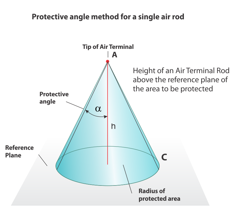
In this method, you must consider the length and position of the air termination rod. This configuration ensures that the conical volume formed by the vertical rod and the angle defined in the standard protects the structure. The coverage area will include the area under the conical volume within the defined angle.
C) Mesh System
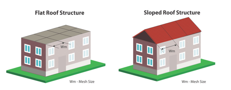
This method uses a conductor to form a mesh over the entire structure. The mesh’s size depends on the protection level, as defined in the standard. The coverage area includes the area of the structure beneath the mesh formed by the conductor.
Defined values of the relevant parameters
The formula for calculating the distance between two Conventional Lightning Arresters(d) According to Rolling Sphere Method
d = 2 * √(2rh – h²)
Where:
- d is the distance between two air terminals,
- r is the rolling sphere radius as per the applied Level,
- h is the air termination height over the horizontal plane.
This formula calculates the maximum distance that can exist between two air terminals to ensure effective lightning protection. It takes into account the radius of the rolling sphere (which varies depending on the level of protection required) and the height of the air terminal above the horizontal plane.
Here’s an example for better understanding. Let’s say for a Level IV protection system, the given values are:
- Rolling sphere radius (r): 60 m
- Height of air terminal (h): 0.5 m
Substituting these values into the formula, we get:
d = 2 * √(2600.5 – (0.5)²) = 15.46 m
This means that for a Level IV protection system, the maximum distance between two air terminals should not exceed 15.46 meters to ensure effective lightning protection.
Talk to our engineers!
ESE Lightning Arrester Coverage Area Calculation
ESE Lightning Protection Systems offer a relatively new approach to lightning hazards. According to the standards (NFC 17-102, UNE 21186), they provide the most effective protection.
The coverage area for the lightning protection system can be calculated according to NFC 17 102-2011. The coverage area falls under the umbrella-shaped semicircle, formed by the protection radius. The height of the ESE arrester, installed relative to the surface and above the structure, is a key factor in this calculation.
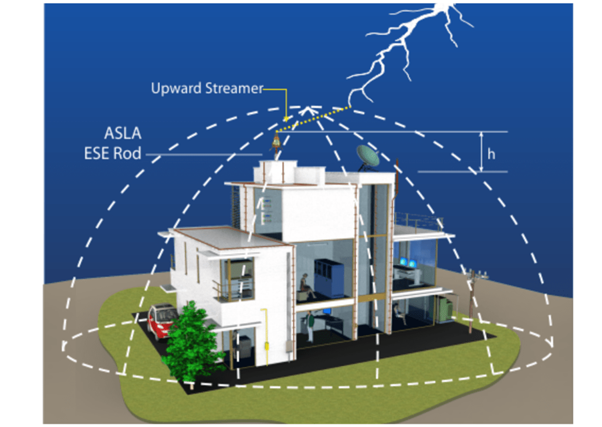
The ESE must be positioned to protect the structure and the area around it. Ideally, you should install it on the highest point of the structure. This positioning maximizes the protection provided by the ESE. An ESE arrester’s efficiency (ΔT) is proved in the evaluation test as per NFC 17 102-2011. The maximum ΔT value is 60 µs.
A Video Tutorial to help you calculate the coverage area:
The calculation for the radius of protection
The protection radius of an ESE is related to its height (h) relative to the surface to be protected, to its efficiency and to the selected protection level, it is calculated with the below formula:
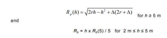
Where,
- Rp (h) (m) is the protection radius at a given height h
- h (m) is the height of the ESEAT tip over the horizontal plane through the furthest point of the object to be protected
- r (m) is 20 m for protection level I | 30m for protection level II | 45m for protection level III | 60m for protection level IV
- ∆ (m) ∆ = ∆T x 106 Field experience has proved that ∆ is equal to the efficiency obtained during the ESEAT evaluation tests

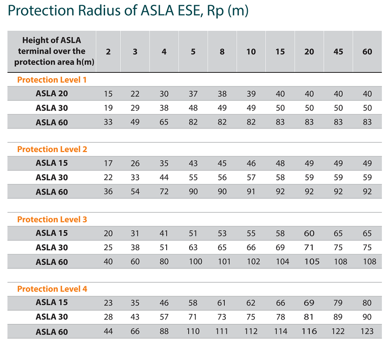
The calculated radius of protection for Axis ESE Arresters
Conclusion
Calculating the coverage area of Lightning Arresters is crucial for designing an effective lightning protection system. It ensures the entire structure falls within the protective zone of an air terminal, reducing lightning damage risk. By considering factors like rolling sphere radius and air terminal height, you can optimally place air terminals, balancing cost-efficiency with comprehensive protection. Correctly determining this coverage area is essential for the safety and longevity of any structure.
Moreover, regular inspection and maintenance of lightning arresters, down conductors, and earthing systems are equally important to ensure continued reliability. Over time, environmental factors can degrade system components, affecting performance. Partnering with a reliable lightning arrester manufacturer and implementing periodic testing while adhering to IEC 62305 or IS/IEC 62561 standards guarantees sustained protection and compliance with safety norms, safeguarding both property and life from the devastating effects of lightning strikes.

FAQ
1. What is lightning arrester coverage area and how is it calculated?
Lightning arrester coverage area refers to the zone within which a structure is protected from lightning strikes. It is calculated using methods defined in IEC 62305, such as the Rolling Sphere Method, Protection Angle Method, and Mesh Method, considering factors like air terminal height, protection level, and spacing between arresters.
2. How does Axis Electricals help in calculating lightning arrester coverage area for projects?
Axis Electricals provides expert support in designing lightning protection systems by helping calculate accurate coverage areas using standards like IEC 62305 and NFC 17-102. Their engineers ensure optimal placement of lightning arresters, improving safety, compliance, and cost efficiency for industrial and infrastructure projects.
3. What is the difference between conventional and ESE lightning arrester coverage area calculation?
Conventional lightning arresters use methods like the rolling sphere and protection angle as per IEC 62305, while ESE (Early Streamer Emission) lightning arresters use protection radius calculations based on height, efficiency (ΔT), and standards like NFC 17-102. ESE systems typically provide a larger coverage area compared to conventional systems.
4. Why choose Axis Electricals for ESE lightning arrester and protection system design?
Axis Electricals is a trusted manufacturer of lightning protection solutions, offering certified ESE lightning arresters with proven performance. Their products are designed to maximize coverage area, ensure compliance with international standards, and deliver reliable protection for substations, industrial facilities, and commercial structures.