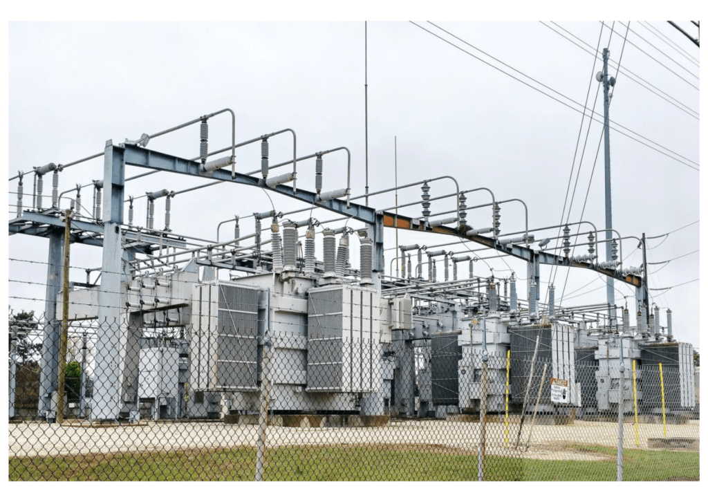
In this trending era of technology and development, earthing in substations plays a vital role. An electrical power system comprises a network of electrical elements that can be used to generate, distribute and transmit electrical energy through transmission lines. A substation is a part of an electrical power system that can transform voltage from high to low or from low to high. This helps in the transmission, distribution, and switching off the power in the system. In this blog, we will understand various aspects of Substation Earthing, including Earthing Materials for Substation, the Role of Earthing in Susbtations, and Parameters for Designing Substations.
There are different categories of substations divided based on the power transfer across the station which include step-up type substations, step-down type substations, distribution type transformers, underground distribution type substations, switchyard, customer substations, and system stations. Let’s start by understanding their importance:
Importance of Substations
Substations are integral to the reliable and efficient operation of the power system. Their importance can be summarised as follows:
Reliability of Power Supply: By monitoring and controlling the flow of electrical power, substations ensure that consumers receive a constant and reliable power supply. In the event of a fault, the substation’s protective devices isolate the faulty section, preventing the fault from affecting the rest of the network.
Efficiency in Power Transmission: Substations play a key role in ensuring the efficiency of power transmission. By stepping up the voltage for transmission and stepping it down for distribution, substations reduce power losses and ensure that electricity is delivered to consumers at the correct voltage levels.
Safety: Through various protective and control equipment, substations ensure the safety of the power system’s operation. They protect electrical systems from damage caused by short circuits and overloads and help protect the public from potential dangers associated with these faults.
Support for Renewable Energy: With the increasing integration of renewable energy sources into the power grid, substations play a crucial role in facilitating this integration. They allow for the connection of renewable energy sources to the grid and manage the variable and intermittent power supply from these sources.
What Is Grounding Or Earthing in Substation?
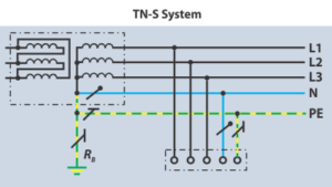
Earthing of a circuit can be defined as physically connecting the circuit with the ground, which has zero-volt potential to the ground (the earth). Grounding of a circuit is holding a circuit to a zero-volt potential but not physically connecting it to the ground. The substation grounding system connects all the equipment, lightning mats, overhead ground wires, surge arresters, and all the metallic structures present in the substation like a network and holds them at the zero-volt potential.
The primary objective of substation earthing is to establish a low resistance path for the dissipation of fault currents, lightning surges, and static charges into the earth. This is achieved by creating a network of conductive materials that connect the non-current carrying metallic parts of the equipment and the neutral points of transformers and generators to the ground. This network is often referred to as the grounding system or the earthing system.
Moreover, the grounding system plays a critical role in the operation of protective devices such as circuit breakers and fuses. During fault conditions, the grounding system ensures that these devices operate correctly, isolating the faulty section of the network and maintaining service continuity in the rest of the system. This is particularly important in preventing damage to equipment and minimizing disruption to the power supply.
Need For Substation Grounding
The major requirements of earthing for a substation are to ensure the safety of the people working in the environment, protection of the equipment in the substation and operational security of the substation. Different requirements that are to be considered for a safe earthing system are:
- Avoiding fatal electric shocks to employees working in the area of earthed facilities during a fault in the power system.
- The currents occurring during normal and fault conditions must be taking a low-impedance path.
- Ground faults must be cleared by improving the operation of the protective relay scheme.
- The reliability of the electric power system must be enhanced.
For calculating the earthing design parameters and the shock potential safety limits, a large variety of national and international standards across the globe are followed, which include:
- BS7354 -1990 Code of Practice for Design of High Voltage Open Terminal Stations.
- EATS 41-24- Guidelines for the design, installation, testing, and maintenance of main earthing stations in substations.
- IEEE Standard 80-2000- Guidelines for AC substation grounding.
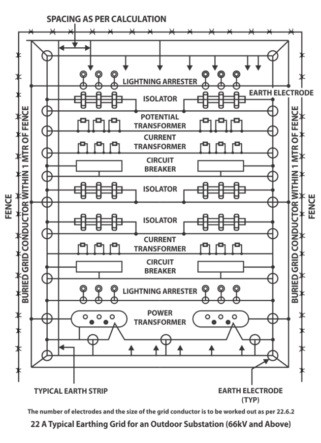
In a substation, all the exposed metal parts, metallic structures, generators, transformers, switchboards, circuit breakers, switches, instrument transformers, lightning arresters, surge arresters, conductors, and reactors are to be grounded using any of the above earthing guidelines so that there would be a proper grounding and there would not be any shock even when there is a fault. For example, a typical substation earthing grid for a 66KV substation is shown below.
Parameters to be considered for the Designing and Construction of a Grounding Network
a) The magnitude and duration of the ground fault current must be computed to select the size of the conductors, straps and connectors used for the protective relay.
b) Random loops and circuits in the network should be avoided.
c) Ground circuit reactance must be reduced by minimizing the separation between the grounding conductors and their respective phase conductors.
d) The return paths of the ground fault current are to be analyzed.
e) The grounding network should be extended to all the island network present within the substation.
Talk to our Engineers!
Methods For Grounding Substation
There are different methods for grounding a substation. The connection to the earth can be made in three ways. They are ring, radial, grid systems.
RADIAL SYSTEM:
The radial system has connections with each of the devices present in the substation paired with one or more grounding electrodes. This method is highly economical but least satisfactory due to the presence of huge surface potential gradients produced during a ground fault.
RING SYSTEM:
The ring system is made up of a conductor that is surrounded by the substation equipment and structures and is connected via short links to each one. This method of substation earthing is economical and efficient as the ground fault currents are given a prearranged path to travel, reducing the surface potential gradient.
GRID SYSTEM:
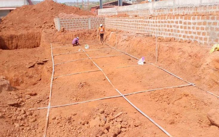
A grid system involves grounding a substation where all the equipment in the substation should be grounded individually, creating an earth mat. An earth mat is an earthing system where all the conductors are buried horizontally forming a grid-like structure to dissipate the fault current into the earth. It forms an equipotential bonding conductor system for maintaining the earth resistance for all the equipment below a specified value. This system is highly effective and expensive compared to the other systems. The grid equalizes the surface potential gradients and protects the people and the equipment from faults.
Complete List of Materials for Substation Earthing
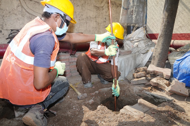
Primary electrode: A ground electrode is specifically designed or adapted for discharging the ground fault current into the ground in a specific discharge pattern, as required by the grounding system design.
Eg. Pipe, Rod, Strip electrodes are used as primary electrodes. They are buried deep into the ground, and they are connected with the wires to the main equipment. Fault current is passed to the ground and dispersed into the earth through these rods. They can be made of galvanized iron or copper.
Ground (Auxiliary) Electrode: It is a conductor embedded in the earth and is used for collecting ground current from the earth or dissipating fault current into it.
Ground Mat: It is a solid metallic plate or a system of closely spaced bare conductors. They are connected to the earth and placed in shallow depths above a ground grid or elsewhere at the earth’s surface. It acts as an extra protective measure by minimizing the danger of exposure to a high step or touch voltage in a critical operating area, or places that are frequently used by people. Grounded metal grating placed on or above the soil surface or wire mesh placed directly under the surface material are common forms of ground mats.
Grounding Grid: It is a system of horizontal ground electrodes that consists of several interconnected, bare conductors buried in the earth, providing a common ground for electrical devices or metallic structures usually in a specific location.
Grounding System: This system comprises all the interconnected grounding facilities in a specific area. It also includes ground electrodes, grounding wires, and earth termination systems.
Conclusion
The earthing system consists of a low-impedance path made up of conductors between the metallic structures and the earth. A predetermined circuit is made available for the ground-fault current to flow through it rather than the random paths. These paths lack mechanical strength and thermal capacity of carrying the fault current and lead to risking the life of individuals, damaging the equipment and in the worst-case scenario they would causing a fire. This network should be made rigid and with no mistakes because, in any case of disturbance in the ground connection, the safety equipment becomes dangerous.
This article is part of our series of articles on Lightning Arresters, Surge Protection & Earthing, you can read more with the following links:
Surge Protection Devices (SPD)
Lightning Protection Zones and their Application to SPD Selection
How does a Lightning Arrester work?
Follow us on LinkedIn for regular updates on our Earthing and Lightning Protection Products!