Expert Electrical
Engineering Articles

Earthing Calculations with Simplified Formulas!

Earthing Calculations

Table of Contents

Electrical earthing calculations are an integral part of electrical protective wiring. There are many pieces of equipment and appliances with metal surfaces around us. These metal surfaces could become energized due to lightning or wiring faults. If they do not have sufficient earthing and a person touches this surface, he will be electrocuted because the current will flow through the person towards the ground. Proper earthing and earthing calculations are important because, in the event of a fault, no persons will be at risk of electrocution, there will be reduced damage to equipment and the amount of time taken to repair the faults is minimized. In designing a building’s electrical installation work various estimations and have to be made through measurements and mathematical & earthing calculations. The results of these calculations enable an engineer to do an electrical design that meets all standards of safety. Earthing is determined by three main factors.

1) The Earth Resistivity

2) Earth Electrode Resistance

3) Earthing Conductors


Important Earthing Calculations

In this blog, we will concentrate on three critical calculations essential for anyone involved in earthing systems. First, we’ll explore Earth Resistivity to understand the ground’s ability to conduct electricity. Second, we’ll delve into Earth Electrode Resistance, a calculation that informs us about the effectiveness of our earthing rod or plate in safely dissipating electrical energy into the ground. Lastly, we’ll examine Earthing Conductors, focusing on the appropriate types and sizes for a reliable system. These calculations are fundamental in establishing both safe and efficient electrical systems. Let’s dive in.


Talk to our engineers!


    Earth Resistivity Measurement

    Earth resistivity (ρ) measured in ohm-meters (Ωm) is the measure of how much soil resists the flow of electricity. To determine this value an earth megger is used using the four-spike method.

    Earth Resistivity

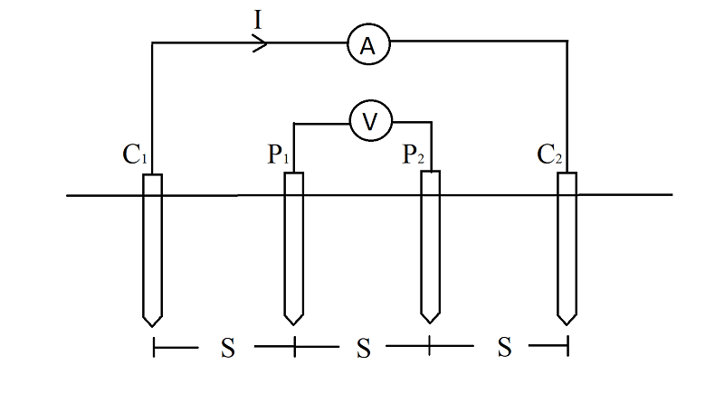
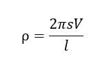
    The resistivity can be obtained with the use of the readings from an earth megger where:

    Earth Resistivity Formula

    •  p = resistivity of the soil in Ω.m
    •  s = distance between two successive electrodes in meters
    • V = voltage difference between electrodes P1 and P2 in volts.
    •  I = current flowing through electrodes C1 and C2 in amperes.
    •  e = depth of burial of electrode in meters


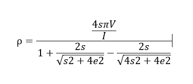
    The depth of burial of the electrode in the ground d is assumed to be negligible compared to the spacing between electrodes. In this case:

    Spacing between Electrodes

    The less the resistivity of the soil the better it is for earthing. The factors that determine this value are:

    Type of soil: Alluvial and clay soils record less resistivity compared to loam and sandy soils. Soils with high amounts of granite and igneous rocks register the highest resistivity to current flow.

    Composition of the soil:  Some soils have a high electrolyte concentration, reducing resistivity. The electrolytes come from salts present in the soil such as Sodium Chloride, Calcium Chloride, Copper Sulphate etc.

    Moisture content: Water increases the conductivity of the soil hence reducing resistivity. Soils in wet climate conditions register lower resistivity than soils in dry conditions.

    Temperature: A decrease in soil temperature especially around the freezing point of water increases resistivity considerably. Temperature changes above 200C have negligible effect on the earth resistivity.


    Catalogue


    Calculation of Earth Electrodes

    Earth Resistivity

    Earth electrodes are supposed to offer zero resistance to current flow while at the same time being resistant to corrosion from the soil under ideal conditions. This is however impossible in practical conditions as electrodes have some resistance and experience corrosion. Copper is the most preferred material to make electrodes because it is a good conductor with high corrosion resistance. The resistance of electrodes is also determined by its shape. For plate electrodes their resistance (R) in ohms is:
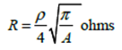
    Earth Electrode Calculation Formula


    where:

    •  p = resistivity of the soil (assumed uniform in Ω.m)
    • A = area of both sides of the plate (in m2)


    For rod electrodes, the resistance is measured using the following formulae:
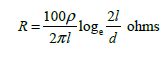
    Earth Rod Resistance Formula

    where:

    • p = resistivity of the soil (assumed uniform in Ω.m)
    • l = length of rod in cm
    • d = diameter of rod in cm


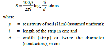
    For strip or conductor electrodes the resistance is measured using the following formulae:

    Strip or conductor electrodes resistance


    Earthing Conductors Calculation

    Earthing conductors

    Earthing conductors enable the flow of current from the building towards the earth electrodes. The material used should have mechanical strength and minimal corrosion with the earth rod. The minimum cross-sectional area for these conductors is 16mm2 (Cu or Fe). The conductors are supposed to be protected from corrosion using protective conductors in the form of:

    • Metal enclosures
    • Sheaths
    • Conductor in multicore cables

    To determine the cross-section of the protective conductors we employ the formula below:

    Earth Electrode Calculation Formula

    Where,

    • S= Cross-sectional area, in square millimetres.
    • I= value (ac, rms) of fault current for a fault of negligible impedance, which can flow through the protective device, in amperes;
    • t = operating time of the disconnecting device, in seconds; and NOTE – Account should be taken of the current-limiting effect of the circuit impedances and the limiting capability (joule integral) of the protective device.
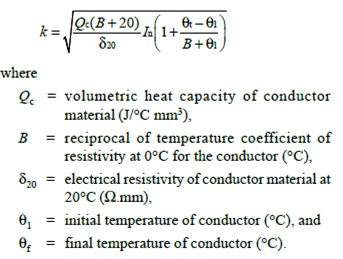
    • k = factor dependent on the material of the protective conductor, the insulation and other parts, and the initial and final temperatures. Values of k for protective conductors in various uses or services for 1 = 1 s and 3 s

    The factor k is determined from the following formula:

    K factor of Earthing conductors


    Conclusion – Why Earthing Calculations matter?

    The critical calculations we’ve discussed—Earth Resistivity, Earth Electrode Resistance, and Earthing Conductors—are not mere academic exercises; they are imperative for the practical design and implementation of robust and secure earthing systems.

    Understanding Earth Resistivity provides invaluable insights into soil conductivity, allowing for a more nuanced and optimized electrode design. Without this knowledge, systems can be over-engineered, leading to unnecessary costs, or under-engineered, resulting in safety hazards.

    Calculating Earth Electrode Resistance enables us to evaluate the performance of our earthing system under fault conditions. The quality of an earthing system is directly correlated with its electrode resistance; high resistance can lead to dangerous touch and step voltages, putting both equipment and lives at risk.

    Earthing Conductors, the physical medium for fault currents, need to be meticulously chosen and calculated to withstand high fault currents for the time duration of the fault. The wrong choice here can lead to overheating and subsequent failure, adding an element of unpredictability and danger to the system.

    In conclusion, these calculations are not just technical jargon but the key players in the effective design, installation, and functioning of earthing systems. Ignoring these calculations can have costly and hazardous repercussions.

    For more information, please contact us at www.axis-india.com/contact-us/


    Related Post
    Earthing & Grounding

    Can Surge Protector Devices protect your EV Charging Stations?

    Earthing & Grounding

    NFPA 780 – A Brief Study On The Lightning Protection Standard

    Earthing & Grounding

    Essentials of Neutral Grounding System