Did you know that 19% of Electricity generated in India is lost while transmitting from the generation plant to the end customer. If you look at Data from the World Bank, the average Electric power transmission and distribution losses for the World was 8% in 2014. Hence, Electric Companies are trying to minimise losses in a transformer. In this blog, we will explore how they do this through Transmission Line Voltage Regulation, let’s start with the basic definitions.
Transmission Line
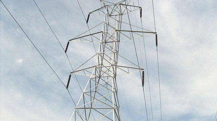
Transmission lines are designed to carry high-voltage electricity, typically in the range of several hundred thousand volts to tens of thousands of volts. They are used to transmit electrical power from a power source to a load, such as the power generation station to the substations and the consumer end.
Voltage Regulation
Voltage regulation is a measure of (losses in a transformer) how much voltage changes along the length of the transmission line i.e. from the sending end to the receiving end.
The performance of the transmission line depends on 4 basic parameters of the line which help calculate the line voltage regulation:
- Resistance (R),
- Capacitance (C)
- Inductance (L) and
- Conductance (G) of the transmission line.
1) Resistance: It is the opposition to the flow of electric current in a conductor, measured in ohms. The resistance is distributed uniformly along the whole length of the line as shown in the diagram on the left.

However, the performance of a transmission line can be analysed conveniently if distributed resistance is considered as lumped as shown in the diagram on the right.
2) Inductance: When an alternating current flows through a conductor, it produces an electromagnetic field around the conductor. This field is known as a changing flux because it is constantly changing as the current alternates. This flux links the conductor, meaning it creates a magnetic connection between the conductor and the surrounding field. Thus, the conductor exhibits a property called inductance. Inductance is a measure of the resistance of a conductor to changes in the current flowing through it.
3) Capacitance: Capacitance refers to the ability of the transmission line to store electrical charge. The line consists of two conductors separated by an insulating material, such as air. The capacitance of the transmission line is determined by the size and spacing of the conductors, as well as the properties of the insulating material – that is air. This capacitance can affect the flow of electrical current in the line by storing and releasing electrical charge and thus help regulate the flow of current and maintain a stable voltage in the transmission line.
4) Conductance: It is a measure of the ease with which electrical current can flow through a material or device. In the context of transmission lines, conductance refers to the ability of the transmission line to conduct electrical current.
Types of Lengths in Transmission Lines

1) Short Transmission Line:
Here, the length of the line is below 80 km, and the line voltage is comparatively low (below 69 kV). Hence the capacitance effects of the line are extremely small and thus neglected. Therefore, the regulation of short transmission lines depends only on resistance and inductive reactance.
Note – Capacitance is the capability of a material object or device to store electric charge.
If the reactance releases energy in the form of a magnetic field, it is called inductive reactance, whereas if the reactance releases energy in the form of an electric field, it is called capacitive reactance.
2) Medium Transmission Lines:
In a medium transmission line, the length of the line is more than 80km, and the line voltage is approximately 69kV to 133kV. The capacitance effects are present in the case of medium-length lines, due to the sufficient length and voltage of the line.
3) Long Transmission Line:
Here, the length of the line is more than 250 km and the operational voltage is very high, more than 133 kV. The performance of such a line is calculated by considering the line constants (which are Resistance, Inductance, Conductance & Capacitance).
The Efficiency of Transmission Lines
Let’s understand the Efficiency of Transmission Lines. Ideally, power generated should be delivered at the substations or consumer end in the same amount. But this does not happen, the delivered power is always lower than expected, resulting in losses in a transformer. This happens because of the Joule effect found in power lines. The energy is lost in the form of heat in the conductors.

Transmission Efficiency
Let’s focus on what exactly is Transmission Efficiency. It is defined as the ratio of receiving end power (PR) to the sending end power (PS), expressed in percentage.
The formula for the same is: % Transmission Efficiency η = PRx100 / Ps %
Voltage Regulation
What is Voltage Regulation in these Lines? The line that carries current has a voltage drop across the length of the transmission line. We often get confused about Voltage drop and power losses in a transformer. Let’s understand the difference:
Voltage drop is the decrease of electrical potential along the path of a current flowing in an electrical circuit. Power loss is the amount of electrical power converted to heat in an impedance.
Thus the receiving end voltage (VR) is usually less than the voltage at the sending end (VS). Therefore, voltage regulation can be explained as a measure of how much voltage is dropped along the length of the transmission line i.e. from the sending end to the receiving end. At a no-load condition, the sending end voltage and receiving end voltage are equal ❲VS= VR❳. But in a practical case, when the transmission line carries current under a loaded condition, the receiving-end voltage decreases compared to the no-load condition. Thus the voltage regulation has a definite positive value. The voltage difference between both the ends is expected to be minimal for an efficient power system.
Performance of the Transmission Line
How can you analyse the performance of the transmission line? Transmission line modelling is a technique used for this analysis. The performance of the line and achieving better voltage regulation is by reducing or compensating for the losses.
In transmission line modelling, equivalent circuits with the transmission line parameters R, L, G and C are considered, and their performance is analysed. Thus the voltage regulation, transmission efficiency and other parameters are determined. The modelling helps in:
a) Estimating the performance of a new system.
b) Estimating the impact on the performance of an existing system, when a new system interacts with it.
c) Estimating the impact of a change of workload on an existing system.
.
How can you improve the Voltage Regulation?
Voltage regulation increases as the length of the cable increases. So it is greater in long transmission lines. One of the ways to improve it, is by controlling the voltage level in the distribution system, but there are limitations.
The continuous long transmission lines can be reduced by having substations, which also help in controlling the voltage level. Some other possible ways include:
a) Installing voltage-regulating equipment in the distribution substations.
b) Balancing the loads on the primary feeders.
c) Increasing feeder conductor size.
d) Changing feeder sections from single-phase to multiphase.
e) Installing new substations and primary feeders.
f) Installing voltage regulators on the primary feeders.
Conclusion
There are different factors which determine the design of a transmission network for efficient transmission of power. Identifying and studying these factors helps in improving the effectiveness of the power network system. It helps to identify various methods and techniques to reduce losses in a transformer. Connect with us at sales@staging.axis-india.com for more details.
Thank you for reading the blog, Axis is a leading manufacturer and supplier of Electrical Components to over 80+ Countries. Talk to our industry expert by visiting our contact us section. You can also watch our videos by our experts – click here.


