Being outdoors, electrical networks are subject to the ravages of nature throughout the year. From lightning, heavy rain, dust or even just local wildlife, these electrical networks become susceptible to faults forming over time.
When these faults occur, outages can take place which can affect large populations of end customers or industrial areas, causing dissatisfaction and revenue losses for the local utility. In our conversations with Utilities and Operations & Maintenance (O&M) firms, in the absence of a fault indicator, the standard practice involves several technicians walking or driving along the length of the line to find the exact location of the fault. In the case of a line such as an Aerial Bundled Cable (AB Cable) where the cables are bunched together, this practice becomes even more difficult as the technicians need to lower the line to find the fault. Additionally, if the fault occurs at night or in highly forested or hilly areas, this endeavour becomes increasingly difficult.
These revenue losses for Utilities and the extra cost of O&M for fault detection have led to the development of products to aid utilities or maintenance firms to quickly detecting faults in their network. A Fault Indicator is a device placed underground or on overground electrical lines to provide utilities with either a visual or remote indication and location of a fault. These Fault Indicators are also referred to as Fault Passage Indicators (FPI), help the utility attain early information on the location of the fault, and take immediate action.

What is an Overhead Line Fault Passage Indicator?
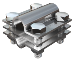
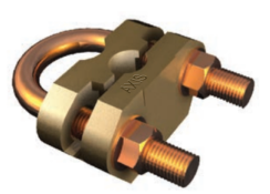
An Overhead Line Fault Passage Indicator detects and indicates faults that occur in an electrical distribution network. It monitors the system 24×7 for fault occurrence and reduces downtime time by quickly identifying the fault location. A Fault Passage Indicator is installed under live conditions with the help of a hot stick and an adapter.
How does a Fault Passage Indicator work?
One Fault Passage Indicator is usually clipped onto each phase of the circuit allowing the utility or O&M firm to monitor current and faults in each phase. By placing the FPI’s at regular intervals along the line, the device can identify faults in the downstream section from its point of installation by monitoring the electromagnetic field surrounding the conductor. During the fault condition, the magnetic field around the conductor increases rapidly as a high current will flow through that path for a fraction of time (di/dt) & then suddenly breaks to zero as the circuit breaker trips, this condition is sensed by the FPI & gives the alarm physically on-site & remotely to SCADA center.
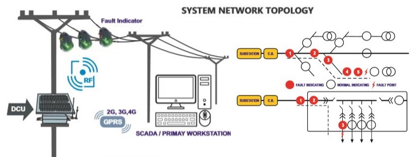
In the case of a non-communicable type, the FPI will give an alarm physically on-site by blinking the RED Ultra bright LED & in the case of a communicable type the FPI gives an alarm physically on-site as well as send the data to the SCADA centre through DCU over GSM/GPRS.
The illustration below provides a basic topology of a communicable system.
The FPI product ultimately aims to reduce the time and effort taken by maintenance technicians to find faults by providing visual and/or remote cues.
When a fault occurs, the fault indicators in front of the fault point will flash an LED to indicate the fault, the ones behind the fault point will not indicate the fault. The operator can easily identify the fault position (between the flashing and non-flashing indicators) by tracking the flashed indicators. It can help the operator to find out the fault point quickly. Permanent fault, transient fault and battery low voltage alarm can be indicated and distinguished separately by 3 different ultra-bright blinking LEDs. Two different alternating ultra-bright blinking LEDs indicate an Earth fault. The parameters such as trip current, reset time, blinking interval, etc. are also read and adjusted over the wireless bidirectional network.
Features of Fault Passage Indicator
Axis Overhead Line Fault Passage Indicator detects an earth fault using the signal injection method with the assistance of a device called signal source. The signal source provides improved accuracy in earth-fault detection. The Axis Overhead Line Fault Passage Indicator is designed as per IEEE 495-2007 international standard. An earth-fault and short-circuit fault indicator consists of three indicators, one for each phase and one for Data Concentrator Unit (DCU) for uploading data to System Server.
Overhead Line Remote Fault Indicators are usually used to monitor short-circuit faults and earth faults. Three ultra-bright blinking LEDs indicate a fault in the network. The information about the fault and the current values can be uploaded to the Server System by utilizing available 2G/3G/4G networks.
Advantages of Fault Passage Indicator
The main aim of an Overhead Line Fault Passage Indicator is to reduce the physical efforts needed to identify the faults & that occur in distribution networks. There is a significant reduction in the time, effort and manpower required for identifying faults.
To know more about our products, click here!
You can also watch our videos by our experts – click here.
Follow us on LinkedIn for regular updates on our Products!