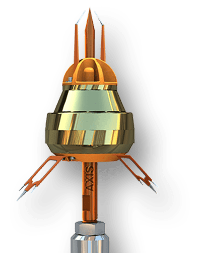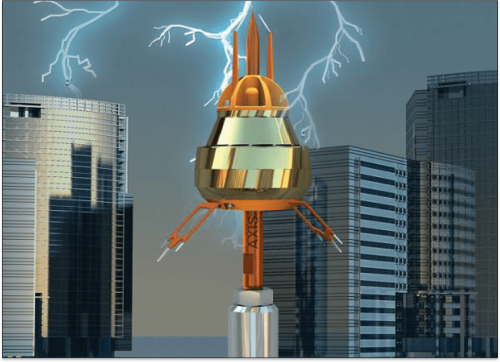

Axis Lightning Arrester’s objective is to become the point of discharge for the lightning bolt, instead of the bolt hitting a random object such as a solar panel or the side of the building. By becoming the point of discharge, the electricity can be safely conducted into the ground using the entire lightning protection system, protecting the structure or solar park.
As per NFC 17-102, the ΔT for an ESE Lightning rrester should be at least 10μs – this means that the emission time of the ASLA ESE is at least 10μs faster than those from a Franklin Rod. Our range of ASLA ESE products ranges from a ΔT of 10μs to 60μs, depending on the requirements of the project.
| Model | Radius of Protection (m) | Height (mm) | Width (mm) | Diameter of Rod Maximum (mm) |
|---|---|---|---|---|
| ASLA 15 | 58 | 321 | 105 | 20 |
| ASLA 30 | 71 | 341 | 132 | 20 |
| ASLA 60 | 89 | 400 | 205 | 25 |
| ASLA 60A | 107 | 400 | 205 | 25 |
The area protected by ASLA is determined using the early streamer emission test method as per NFC 17 102 Standard and it is preferred to have ASLA installed on the highest part of the structure.
The protected area is delineated by a surface of revolution defined by the protection radii corresponding to the different considered height h and which axis is the same as the one of the air terminal as per the below figure, (source: NFC standard).

The ASLA system is based on the time difference (ΔT) between the emission time of a conventional lightning arrester and an early streamer emission lightning arrester, as demonstrated in high voltage testing laboratories. This emission from the ESE is generated by storing energy from the ambient electromagnetic field or static charges at the time of the lightning events.
In normal conditions, the air terminal stays in standby mode. However, there is a spike in the ambient electrical field when a storm approaches the site. This spike causes the timely release of the stored energy, generating an upward leader from the tip of the ESE lightning arrester. This upward leader moves toward the downward leader from the storm clouds, creating a path for discharge. The bolt then passes safely through the conductive body of the ESE Lightning Arrester to the down conductors and finally safely into the ground, protecting the building or solar project. This working principle allows for an enhanced radius of production provided by Early Streamer Emission Lightning Arrester than by a conventional lightning rod.
Axis Smart Lightning Arrester (ASLA) is composed of one main striking point, emission device, fixing element, and a connection to the down conductor.
The area protected by ASLA is determined using the early streamer emission test method as per NFC 17 102 Standard and it is preferred to have ASLA installed on the highest part of the structure.
The protected area is delineated by a surface of revolution defined by the protection radii corresponding to the different considered height h and which axis is the same as the one of the air terminal as per below figure, (source: NFC standard)

The protection radius of an ASLA is related to its height (h) relative to the surface to be protected, to its efficiency, and to the selected protection level.

for ≥ 5m
for 2m ≤ h ≤ 5m
where,
| Rp | = | Protection radius of ASLA at a given height h (m) |
| h | = | Height of ASLA tip over the area of reference plane considered |
| r | = |
|
| Δ | = | Initiation advance equivalent to efficiency of ASLA as per below(m)
|

AXIS House, Plot# 149-BCD,
Kandivali Co-Op Industrial Est. Ltd., Kandivali (W), Mumbai – 400067,
India.
© Copyright Reserved by Axis Electrical Components (India) Pvt. Ltd.

Get Your Free Book Now!
