Lightning protection for buildings is a very crucial aspect of safety. The Rolling sphere method is one of the three routes for lightning protection system design defined by IEC 62305, the international standard for lightning protection design. After the first step of determining the class of lightning protection decided by the Risk Assessment, the lightning protection for buildings and system design can be done using the Rolling Sphere, Protection Angle method or the Mesh method. The system design will provide information such as the location of the lightning arresters, down conductors, earth electrodes, other equipment, and the complete Bill of Material.
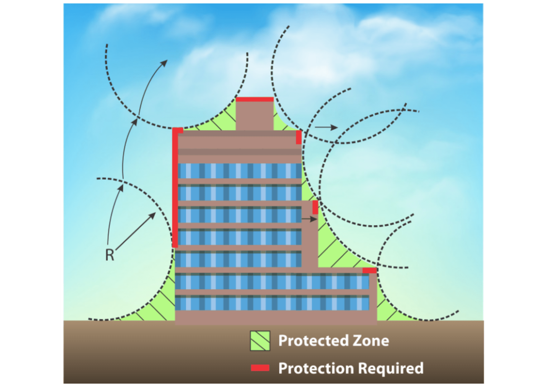
The Rolling Sphere Method is an aid to identify the areas of a building or structure that needs protection using air termination rods. This method also takes into account the possibilities of strikes to the side of the building. As illustrated below, a sphere, with a radius defined by the Class of LPS, is rolled across a structure. Wherever the surface of the sphere comes into contact with the structure is deemed to be unprotected, thus requiring air termination.
The table below shows the radius of the rolling sphere for different classes of LPS. As we can see in the table, Class I has the smallest rolling sphere radius and as a result, this smaller sphere would touch parts of the building (deemed unprotected) that the larger spheres would not touch (deemed protected). Thus, structures with Class I protection have the highest level of protection.
While side strikes could occur on buildings that are higher than the radius of the rolling sphere, the probability of these side strikes is negligible on structures less than 60m in height.
The Rolling Sphere also allows designers to divide the outer structure into distinct Lightning Protection Zones, LPZ0A and LPZ0B. As discussed in our blog, “Lightning Protection Zones and their Application to SPD Selection”, IEC 62305 Part 4 defines these Lightning Protection Zones as shown below.
Zone 0: Zone where the threat is due to the unattenuated lightning electromagnetic field and where the internal systems may be subjected to full or partial lightning surge current.
LPZ 0 is subdivided into:
LPZ 0A: Zone where the threat is due to direct lightning flash and full lightning electromagnetic field. Internal systems may be subjected to full lightning surge current.
LPZ 0B: Zone protected against direct lightning flashes but where the threat is the full lightning electromagnetic field. The internal systems may be subjected to partial lightning surge current.
Separation Distance Between the Air Termination Rods
When multiple air termination rods are to be used to protect a plane surface, the following equation can be used:
d=2√(2rh-h^2 )
d = separation distance between the rods (metres)
r = radius of the rolling sphere (metres)
h = height of the rods (metres)
Penetration Distance of a Rolling Sphere
When designing the air termination system for a building or for a roof-mounted structure, the penetration depth of the rolling sphere between two air termination rods becomes a decisive factor.
p=r-√(r^2-(d/2)^2 )
p = penetration distance (meters)
r = radius of the rolling sphere (meters)
d = distance between two air termination rods
As you have read above, assessing, designing and finally constructing a safe and reliable Lightning Protection for buildings is not an easy task. It requires many measurements, calculations, and experience to execute perfectly. In addition to the products and 25 years of experience that Axis offers, we also offer a software suite that will help simplify all your lightning protection calculations so that you can put your head towards providing the best service for your clients. Axis can also help you with the entire process from Step 1 of Risk Assessment to Lightning Protection System Design and all the way through the supply of internationally approved products. Our engineers will be on the field with you to make sure that they provide the most precise protection for your structure!
This article is part of our series of articles on Lightning Protection, Surge Protection & Earthing, you can read more with the following links:
Surge Protection Devices (SPD)
Lightning Protection Zones and their Application to SPD Selection
How does a Lightning Arrester work?
Origin Researchers and engineers in the mid-20th century pioneered the concept of heat shrink tubing…
Originally, insulators were made from materials like ceramic and glass. But in 1963, a new…
Why is understanding the difference between Surge Arrester and Lightning Arrester crucial? Did you know…
Do you know what helps maintain the safety of you and your electrical appliances from…
In this blog, we will understand the surge risks faced in EV charging stations and…
For safe electrical earthing and bonding, the choice of an appropriate Rod Earthing is pivotal…