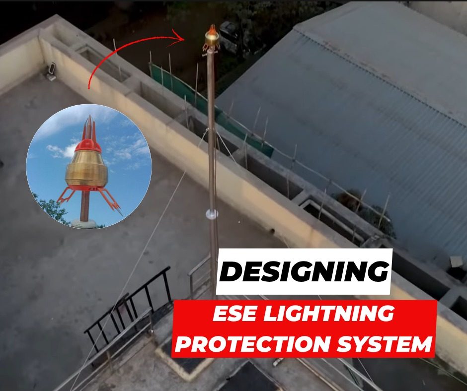
In this blog, you will understand the basics of designing an ESE lightning protection system.
Before installation you must understand the basic design steps involved.
Check how exposed your structure is to lightning and what will happen if it gets struck. You start by looking at:
If your site is in a region with high lightning density, your probability of being struck is naturally higher. Areas with frequent thunderstorms demand a higher level of protection compared to areas with lower lightning activity.
Next, you evaluate the physical characteristics of your structure. If your building is tall, isolated, or located on elevated ground, it is more likely to initiate an upward leader and attract lightning. An upward leader is a rising spark from the structure that connects with lightning coming down from the cloud.
Then you must consider how the structure is used. If your facility is a hospital, data centre, telecom site, industrial plant, or fuel storage area, the consequences of a lightning strike are severe. In such cases, you cannot accept even moderate risk. Your protection level must be higher.
Based on all these factors, you determine your required protection level: level one, two, three, or four. Level one gives you the highest degree of protection, while level four provides a lower but still controlled level.
This decision is critical. If you underestimate the risk, your system may fail during an actual lightning event. If you overestimate it, you may spend more than necessary. Therefore, risk assessment is mandatory.
After you complete the risk assessment and decide the protection level, you select the ESE lightning arrester based on the calculation.
According to NFC 17-102, the protection radius of an ESE depends on three things:
The protection radius is the horizontal distance around the arrester that remains protected. If you install the arrester higher, the radius increases. If you choose a higher protection level, the radius becomes more conservative, however it provides an umbrella protection.
Delta T represents how much earlier the device emits the upward leader compared to a conventional rod. It is measured in microseconds. For design as per NFC, Delta T can be between 10 and 60 microseconds.
You calculate the protection radius using this formula. Then you check if that radius fully covers your structure. If the calculated radius does not cover the entire building, you cannot assume protection. You must either increase the height or add another arrester.
So, selection is not about choosing a model at random. You calculate, verify the coverage, and then finalise the device.
Place the arrester at the highest point of the structure. This gives you the largest protection radius for a given height and protection level.
Next, match the placement to the shape of the structure. A long roof, multiple levels, or separate blocks can leave corners and edges outside the covered zone. So, place the arrester where the calculated protection radius covers the full structure.
Then check the surrounding area. If you have a nearby object that sits higher, such as a tower, mast, or another building, lightning will prefer that point. After placing the ESE, keep a clear and direct path for the down conductors to reach the grounding system.
The lightning current must travel from the ESE to the ground through a safe path, which is why the design of down conductors is a critical step.
In an ESE system, you connect each air terminal to at least two down conductors. You use two so the lightning current divides and reduces stress on a single path. Install them at opposite sides of the structure. This spreads the current flow and reduces the chance of side flashing on one side.
Keep distance from other metal parts and internal cables. Lightning can jump to nearby conductive parts if they sit too close. The aim is simple: give lightning a direct path to earth, so it does not travel through your structure.
Lightning current must enter the soil in a controlled way. If the current cannot disperse into the ground, it will be a threat for your structure and equipment.
You connect each down conductor to an earth electrode system. This gives the lightning current a direct path into the soil. Ensure the earth electrodes are properly interconnected. This keeps your system at the same potential during a strike and reduces the risk of side flashing. The required earth pit resistance shall be less than or equal to 10 ohms.
Hope you now have a brief idea of how an ESE lightning protection system should be designed. Please note, these calculations and designs should only be carried out by a competent or authorised engineer.
At Axis, our team of 50+ engineers are ready to assist you with designing, installing, and testing your Lightning Protection Systems. Our products have been used in substations, data centres, factories, and in everyday residential and commercial buildings.
Thank you for reading and if you found this informative, then feel free to contact us to get a quote or to know more about our products; visit our product section at https://axis-india.com/products/
Split bolt connectors join conductors and carry current through the connection point. If the joint…
You are working on a live line and taking a connection using an Insulation Piercing…
Your PV modules are the most exposed and most critical part of your solar plant.…
Have you ever noticed how cables safely enter and exit electrical enclosures? This is made…
Heat shrinkable products are polymer components that shrink when you apply heat. During manufacturing, we…
A Termination Kit is used to safely connect a cable to equipment like switchgear, transformers,…