Aerial Bunched Cable (ABC) is an innovative concept for Over Head power distribution. When compared to the conventional bare conductor OH distribution system, ABC provides higher safety and reliability, lower power losses, stability in terms of voltage regulation and ultimate system economy by reducing installation, maintenance and operation costs. This system is ideal for rural distribution and especially attractive for installation in difficult terrains such as hilly areas, dense forest, coastal regions etc. This line can be laid without cutting or trimming any trees. ABC is also considered to be the best choice for power distribution in congested urban areas with narrow lanes and bylanes. It is convenient to lay it in thickly populated areas with dwelling having narrow gaps between buildings, where it is not possible to run bare conductors. Also, accidents due to electrocution are prevented. This system has a distinct advantage in terms of cost of laying compared to underground cables. Underground cable installations are more expensive to install than overhead lines, with a capital cost ratio as high as 20:1. Also since it is clearly visible; the faults can be detected and rectified quickly with ease. Also, damage due to waterlogging is avoided, unlike underground cables.
Check our range of AB Cable Accessories
AB Cable is formed by twisting together insulated phase conductors of aluminium around a bare or insulated messenger made up of aluminium alloy, which acts as a supporting system and also serves as a neutral or earth conductor. This assembly is directly strung onto distribution poles/towers or building facades by means of standard hardware. They are available in three basic configurations:
1. Four core systems
2. Insulated messenger wire system
3. Bare messenger wire system
The Indian Bureau of Indian Standards has backed IS 14255 as the standard for Aerial Bunched Cable. This standard recognizes bundled cables with bare and/or insulated messengers. This has led to much confusion as the hardware required for both are different in design and application. Also, section 6 of IS 14255:1995 states that the standards for accessories which are in common use are in consideration and will be issued shortly. However, no standard has been formed so far.
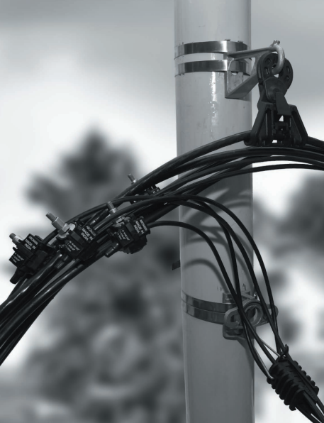
Anchoring Assembly: The entire bundle is supported on the pole by the anchoring clamp. All four conductors are clamped together inside the anchoring device where the load of the entire bundle is distributed on each conductor. This assembly can be fixed on the pole with the help of suitable brackets or bolts.
Suspension Assembly: A suspension clamp is used to hold the entire bundle of four core systems on the pole with the help of a suspension bracket or hook bolt through the pole.
Anchoring Assembly: In this system, an anchoring clamp is used to hold only the bare messenger and not the entire bundle. This assembly is fixed on the pole with the help of a PCC pole clamp and eye hook.
Suspension Assembly: Similarly suspension clamp is used to hold only the bare messenger wire which takes the load of the entire bundle. This assembly is fixed on the pole with the help of a PCC pole clamp and eye hook.
Anchoring Assembly: The anchoring clamp is made up of an aluminium alloy outer body with inner wedges of UV-stabilized thermo-plastic to avoid damage to the insulation of the messenger wire. The clamping of the messenger wire is done in such a way that no other mechanical components are required. Anchoring brackets and stainless steel straps are used to hold the assembly on the pole. The most commonly used standard for anchoring assembly is NFC 33 041.
Suspension Assembly: The suspension clamp is made of UV-stabilized thermo-plastic glass reinforced. A specially designed weak link also called a fuse link is provided to allow the breakage of the hardware rather than the snapping of the cable. The entire assembly is fixed on the pole with a suspension bracket and stainless steel straps or bolts. The most commonly used standard for suspension assembly is NFC 33 040.
This method is used in the following situations like road crossing & single service supply. After ensuring that the ground is free from sharp objects, the whole ABC cable is laid on the ground and its ends are connected to a hauling rope. Suspension or anchoring devices are fixed on intermediate poles and temporary pulleys are hung on top of them. ABC cables are tensioned until reaching the required sag. Then the cable is anchored or suspended to each pole span by span and the pulley & winch are taken out.
This is the most commonly used method in the erection of ABC networks as it is quick and fast. It can be done in the following steps:
The suspension or anchoring devices are fixed on an intermediate pole along with a temporary pulley.
The hauling rope is run through each pulley. One end of the rope is connected to the ABC cables using a swivel and pulling grip, while the other end is connected to an automatic winch on the ground.
The winch pulls back the hauling rope and then the ABC cable. At the same time, a breaking device on the cable drum carrier prevents the ABC cable from slipping back till the cable reaches the end pole. Lastly, the ABC cable is anchored or suspended to each pole and the pulleys are taken out.
Slack tension can lay cable on more spans while in the layout method number of spans is limited.
The slack method saves time as more time is spent in the layout method to adjust & fix the manual winch or to lift the cable manually.
The slack method saves the ABC cable from damage caused by sharp edges or objects on the ground and while lifting. Parameters for sag and tensioning of the cable bundle will depend upon ambient temperature, and the distance between the poles i.e. span, cable configuration and weight.
Insulation Piercing Connections: The IPC is used to tap the ABC networks to the service line. This is the most critical component in an AB line as it establishes electrical continuity without the need to strip the insulation and hence can be used on a live line. The construction allows the joint to be completely sealed for any water ingress, thus preventing any damage to the conductor in the long run.
Preinsulated sleeves: The preinsulated sleeves are used to connect two low-voltage ABCs. It is used in the installation, repair or replacement of the connection.
Preinsulated lugs: The preinsulated lugs are friction welded with copper palm and aluminium barrels. It is used to connect the ABC cable to an equipment terminal. The dielectric strength underwater is over 6KV.
With all these advantages, it is apparent that AB lines are most suitable for urban as well as rural India. This fact is well recognized by many nodal agencies like Power Grid, REC & BIS. Several distribution companies in Rajasthan, West Bengal, Orissa, Gujarat etc. have taken the lead and started implementing Bundled Conductor Lines. Wherever implemented, there has been a substantive reduction in power loss, sometimes up to 40%. However, the initiatives taken are scattered leading to unplanned, haphazard development and serious mismatch of product specifications.
Most contractors have been expressing dissatisfaction about the quality and timely availability of the material, leading to delays in the projects. Lack of coordinated effort and the absence of a central agency supervising the efforts resulted in different SEBs adapting the product specifications directly from available international standards. Let us quickly examine the root cause of these issues.
Traditionally, as we have been using an open wire system, over a period of time all the people working on this system have developed a good understanding of the checks during installation. A major concept in open wire systems, the accessories used are of equal or more than the mechanical strength of the cables being suspended. This is good for an open-wire system. When it comes to the AB cable system, this concept needs to be changed and in fact, this change of concept is taken care of in various standards, particularly the French std, who are the major users of the system.
Now, since the cables are insulated, taking care of the insulations by the grips provided by various accessories is of paramount interest. This is the main reason why the standard says that the mechanical strength of the accessories employed on the AB cable system should be lesser than the ultimate mechanical strength of the AB cable being used.
The logic behind this is since we can do live line working on the AB cable, the AB cable needs to be protected from snapping which can happen if the mechanical strength of accessories is more than the AB cable. This also justifies the fact that snapping of the cable means a loss of power to the connected units and thereby a loss of revenue.
In the French std, accessories are designed to be weaker in mechanical strength thereby if there is a failure of accessories; it is only the cable which drops out from those points, which can be re-laid by using new accessories without power disruption and without loss of revenue. Like any product variant, there are several variants of this technology evolved in different countries. It is highly essential for all potential users in India to understand the “core” of the new technology & tailor it to match our regional, technical & environmental conditions.
Thank you for reading the blog, Axis is a leading manufacturer and supplier of AB Cable Accessories and other Electrical Components to over 80+ Countries. To get a quote or to talk to our industry expert visit our contact us section. You can also watch our videos by our experts – click here.
Earth resistance is the measure of how easily electric current can flow from an electrode…
Lightning arrester rods, surge arresters, or lightning conductors are metal rods installed on a building…
Follow us on LinkedIn for the latest updates The protective angle method is one of…
In this trending era of technology and development, earthing in substations plays a vital role.…
The electrically conductive connection between the air-termination system and the earth-termination system is the down…
In this blog, we're focusing on the essential differences between Galvanised Iron Pipe Earthing, also…