Over the past century, Electrical Safety Standards have evolved into highly advanced frameworks, covering all key aspects of safe installations, including Earthing Systems. For Low-Voltage (LV) Electrical Installations, the IEC 60364 standard ensures the protection of both personnel and property.
The IEC 60364 standard defines three main types of Earthing Systems: TT, IT, and TN. As IEC leads the global standards in electrical, electronic, and related technologies, the IEC 60364 standard serves as the highest authority for LV Electrical Installations worldwide. Consequently, many national standards recognize the three types of Earthing Systems outlined in IEC 60364. For example, the UK uses BS 7671: 2008 (IEE Wiring Regulations 17th Edition), and India follows IS 732:1989 (R2015).
The IEC 60364 standard defines the following Earthing Systems:
TT
IT
TN (with further subdivisions: TN-C, TN-S, TN-C-S)
For clarity, we refer to five types of Earthing Systems that are common worldwide.
Watch Our Video for a Detailed Explanation of all the 3 Systems!
The first letter in each system refers to the power source from a star-connected winding, while the second letter refers to the consuming equipment that requires earthing.
From the ‘Handbook of Electrical Engineering: For Practitioners In The Oil, Gas And Petrochemical Industry’ by Alan L. Sheldrake
T means that the source’s start point is directly connected to earth.
I indicates the source’s start point is isolated from earth, typically through an inductive impedance or resistance.
N refers to the neutral conductor, which is connected to earth.
S means the neutral and protective conductors are separated, requiring five conductors for a three-phase system.
C means the neutral and protective conductors are combined, requiring only four conductors for a three-phase system.
T = Direct connection to the Earth, T stands for Terra meaning earth
I = Isolated
N = Neutral
S = Separate
C = Combine
The most common systems used are TT and TN. Some countries, such as Norway, use the IT system. A summary of the Earthing Systems used for public distribution in different countries is shown below.
In the TT system, the supply source and the installation’s metalwork directly connect to earth. For overhead lines, the earth mass acts as the return path for the line. The installation must keep the neutral and earthing conductors separate, as the power distributor provides only the supply neutral or protective conductor.
The IT system does not directly connect to earth or connects through a high impedance. The key feature of the IT system is its ability to continue operating if a fault occurs between phases and earth. It is known as a ‘first fault.’ This allows the system to remain functional while other protections fail. Power distribution in substations or generators typically uses the IT system.
In the TN-S system, the system keeps the ground and neutral conductors separate throughout the distribution. The metallic covering of the cable supplying the installation serves as the protective conductor. The system connects all exposed conductive parts of the installation to this protective conductor or via the main earthing terminal.
You can read our detailed article about the TN-S Earthing System to learn more.
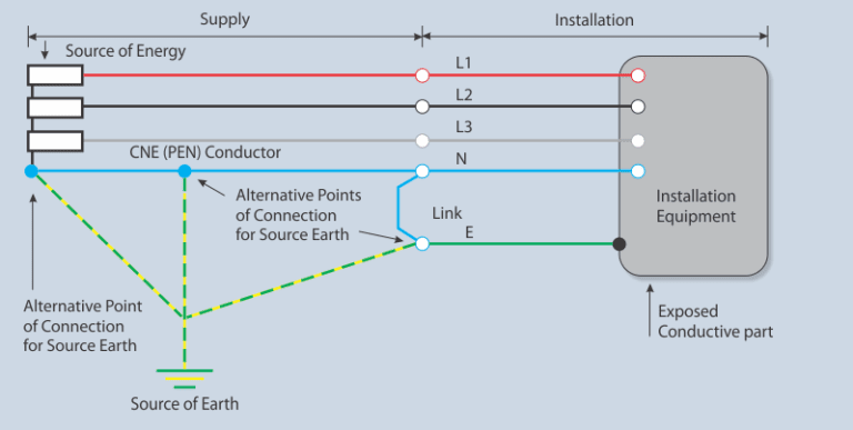
In the TN-C system, the system combines the neutral and protective earth conductors into a single conductor. The PEN conductor connects all exposed conductive parts of the installation. According to the Electricity Safety, Quality, and Continuity Regulations 2002 (8(4)), consumers must not combine neutral and protective functions into a single conductor within their installations.
The TN-C-S system combines the neutral and protective earth conductors in a single conductor at certain points in the system. This system, known as multiple protective earthing, involves earthing the supply system PEN conductor at two or more points. A near consumer’s installation may require an earth electrode. The PEN conductor connects all exposed conductive parts to the main earthing terminal, where it links the neutral and protective earth terminals.
Conclusion
Understanding the differences between TT, IT, and TN earthing systems is essential for ensuring electrical safety, reliability, and compliance with global standards such as IEC 60364, BS 7671, and IS 732. Each earthing type—whether TT with its independent earth connection, IT with isolated neutral, or TN systems (TN-S, TN-C, TN-C-S) with varying conductor configurations—serves specific operational and safety requirements depending on the installation environment.
Selecting the right earthing system not only protects personnel and equipment from electrical faults but also ensures efficient fault clearance and system continuity. When properly designed and maintained, an effective earthing system forms the backbone of any safe electrical installation.
You can view our wide range of Earthing, Grounding and Bonding Equipment here. You can contact us if you want a quotation or have any further questions regarding the products required for Earthing, Grounding, or Bonding.
This article is part of our series of articles on Lightning Protection, Surge Protection & Earthing. You can read more with the following links:
Introduction to the basics of Lightning Protection and Earthing and the Standards (IEC 62305 and UL 467)
Surge Protection Devices (SPD)
Lightning Protection Zones and their Application to SPD Selection
How does a Lightning Arrester work?
For more information, please contact us at axis-india.com/contact-us/
Nowadays, the world is spending billions of dollars on building new solar plants. Some of…
Eye hooks are critical fittings used with dead-end and suspension clamps to support Aerial Bundled…
In this blog, we will discuss some common mistakes most people make while installing earthing.…
Suspension clamps are used to suspend and grip neutral messenger cables in Low Voltage Aerial…
The International Electrotechnical Commission (IEC) prepares and publishes International Standards, such as IEC 62305, for…
In this blog, we will talk about the tools required for installing MV Covered Conductor…