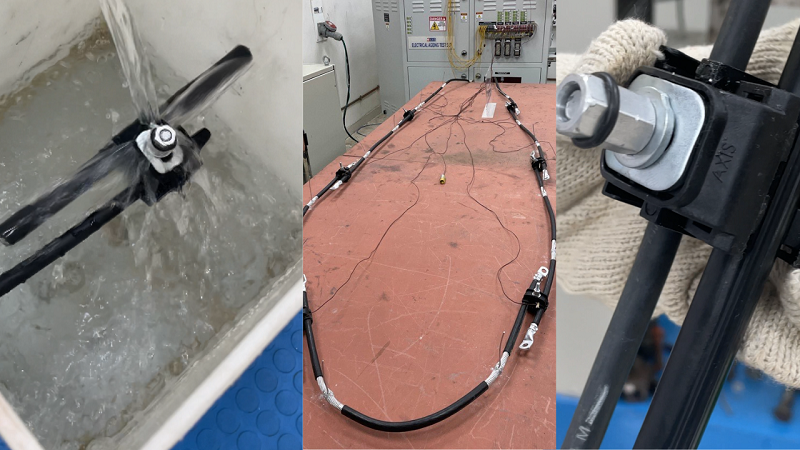
In the electrical distribution, ensuring the quality of Insulation Piercing Connectors (IPCs) is crucial. IPCs, used extensively in AB cable systems, need to pass rigorous tests to guarantee their efficiency and safety in various applications. This guide delves into six key tests based on the French Standard NFC 33-020 2013, providing a comprehensive understanding of each test’s purpose, methodology, and importance.


What are Insulation Piercing Connectors?
Known as IPCs, Insulation Piercing Connectors are used in all AB cable systems. They create tap connections that can extend the line, distribute the line, connect to street lights, or connect to households.
These connectors come with a water-resistant design that seals the connection, guarding against water penetration. Low-quality IPC’s allow water to enter the cable and this can cause issues like short circuits and metal corrosion that will compromise the entire electrical system.
Additionally, the connectors are designed to eliminate the need for insulation stripping. This makes the installation process quicker than in traditional bare conductors. This feature also reduces the likelihood of tampering or theft.
However, to establish reliable and durable electrical connections, these IPCs need to be of high quality. But how do you ensure quality for IPC’s? The French Standard NFC 33-020 2013 specifies the testing requirement for these products.
6 Critical Tests for assessing the quality of IPCs
1. Continuity Test


A fundamental aspect of IPC quality is ensuring electrical continuity. This test verifies the presence of a complete path for current flow through the connector. Using either a continuity tester or a meter with a continuity beeper, the presence of a glowing light indicates proper continuity, confirming that the IPC has established correct connections at both ends of the cable.
2. Shear Head Break Test


This test ensures that the shear head of the connector breaks at a specific torque, indicating correct installation. Incorrect torque application can lead to loose connections or conductor breakage, leading to system failure. A successful test shows the shear head breaking within the predefined torque range.
Talk to our engineers!
3. High Voltage Test


IPCs must withstand high voltages, particularly during fault conditions. This test involves applying a high voltage (e.g., 6kV) to the IPC for a specific duration (e.g., 60 seconds). Failure of the IPC to sustain this voltage level indicates a lack of insulation integrity.
Here’s a video showing the correct procedure of conducting all these tests.
4. Tensile Test


The tensile test assesses the connector’s ability to withstand required tensile loads without damaging the connected cable. After applying the specified load for a set duration (as per NFC 33 020 2013), the IPC should remain undamaged, and the conductor should not slip from the connector.
5. Water Tightness Test


To prevent water-induced short circuits and metal damage, IPCs must be watertight. In this test, the IPC is submerged in water for 24 hours, with a portion of the conductor inside and outside the water at the same level. The absence of watermarks or traces at the core ends after this period confirms the IPC’s water tightness.
6. Electrical Aging Test


This long-term performance test involves connecting multiple IPC samples with cables in a series to form a test loop. The test evaluates the functional properties of the connectors and a reference conductor at elevated temperatures (up to 120 degrees Celsius). After repeated heating and cooling cycles, the IPCs must meet standard criteria for resistance and temperature, indicating their longevity.
While these tests ensure the quality of IPCs, proper installation is equally crucial for their performance. Inadequate installation can contradict even the most rigorous testing, emphasizing the need for adherence to correct installation procedures.


Have a look at the correct installation process here
At Axis, we subject our IPCs to these comprehensive tests in our NABL-accredited and UL-approved Testing Lab. We understand that millions of Axis IPCs installed worldwide depend on our unwavering commitment to quality.
Thank you for reading the blog, Axis is a leading manufacturer and supplier of Electrical Components to over 80+ Countries. Talk to our industry expert by visiting our Contact Us section. You can also watch our videos by our experts – click here.
Follow us on LinkedIn for regular updates on our Products!
