Scope:
The primary reason for earthing in an electrical network is for safety. When all metallic portions of electrical equipment are grounded, there are no harmful voltages present in the equipment case. If the live wire comes into contact with the grounded case the circuit is effectively shorted, and the fuse will blow. When the fuse blows, the harmful voltages are no longer present.
The objective of Earthing:
Human Life/Building/Equipment Safety:
By blowing a fuse, it saves human life from the dangers of electrical shock or death, i.e., by providing an alternate path for the fault current to flow so that it does not imperil the user.
To safeguard structures, machinery, and appliances in the event of a failure. To ensure none of the exposed conductive elements reaches a harmful voltage.
To offer a safe path for lightning and short circuit currents to dissipate. To provide a stable platform for the operation of sensitive electronic equipment, i.e., to maintain a known voltage at any portion of an electrical system to avoid overcurrent or excessive voltage on appliances or equipment.
Protection against overvoltage:
High voltages in the electrical distribution system can occur by lightning, line surges, or unintended contact with higher voltage lines.
Earthing provides an alternative channel around the electrical system to reduce system damage.
Stabilization of voltage:
Electricity comes from a variety of sources. Every transformer can be its source. It would be difficult to calculate the relationships between these voltage sources if it lacks a common reference point.
Because the earth is the most pervasive conductive surface, it was accepted as a practically universal standard for all-electric systems from the beginnings of electrical distribution networks.
Methods of earthing:
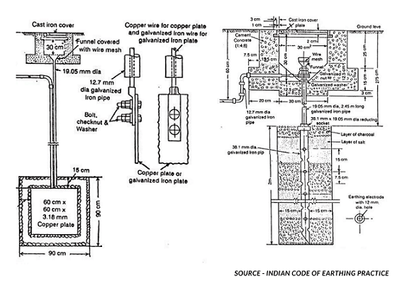
Iron/Copper Plate Earthing:
Cast iron plates measuring 600 mm x 600 mm x 12 mm for plate style earthing OR a 600 mm × 600 mm x 6 mm galvanised iron plate OR a copper plate with dimensions of 600 mm x 600 mm x 3.15 mm.
The plate is buried vertically at a depth of 8 feet, and a GI strip of 50 mm x 6 mm bolted to the plate is pulled up to ground level.
Up to 4 feet from the bottom of the pit, these earth pits are usually filled with an alternate layer of charcoal and salt.
Pipe Earthing:
GI pipe [C-class] of 75 mm diameter, 10 feet long, welded with 75 mm diameter, GI flange with six holes for the connection of earth wires, and insertion in the ground by auger method is the standard practice for pipe type earthing.
These earth pits are filled using an alternate layer of charcoal and salt or an earth reactivation mix.
GI Plate Earthing:
Galvanized Iron (GI) pipe is an earth electrode for earthing house wiring, factory wiring (especially electrical installations in large industries), neutral wire of the supply line, and other applications.
The pipe’s size is determined by the fault current and the soil’s condition. If moist and soft soil is present in the earth pit, the pipe should be at least 2 metres long with a diameter of 38.1 mm, according to the Indian Code of Practice.
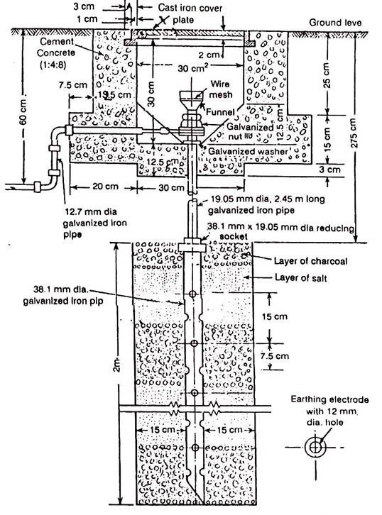
Source - Indian code of earthing practice
The length of the pipe should be increased to 2.75 metres if the soil is dry and rocky. In such cases, 12mm diameter holes are drilled into the pipe at equal intervals with its length for excellent contact between the inner surface of the pipe and the earth.
Galvanized iron wire or strip is used as an earth lead, while the pipe is an earth electrode. The maximum current that will flow through the earth wire when a fault occurs will determine the size of the earth wire. The cross-section of this wire, on average, is 0.645 square centimetres.

Copper Plate Earthing:
According to Indian Standard, if a galvanised iron plate is used as an earth electrode, its dimension must not be less than 60 cm × 60 cm x 6.35 mm (2 ft x 2 ft x 12 in). As an earth lead, galvanised iron wire is with this plate.
In the case of a copper plate earthing, the plate must be at least 60 cm × 60 cm x 3.18 mm (2 ft x 2 ft x 18 in) in size, with copper wire serving as the earth lead. The plate is inserted vertically in the earth hole at a depth of at least 3 metres (10 feet), below ground level in both circumstances.

Source - Indian code of earthing practice
Soil’s condition determines the depth of the plate in the earth pit. It must be placed in a constantly damp environment. The earthing becomes a source of risk if the soil surrounding the plate gets dry and hard. As a result, it is vital to test the earthing system regularly.
Importance of Earth Resistance in GI and Copper Earthing:
When an earth electrode system is developed, the earth resistance between the electrode and “Real Earth” must generally be measured and confirmed. The 3-point measuring technique is the most frequently used method of determining an earth electrode’s earth resistance.
The earth tester terminals C1 and P1 are shorted and connected to the earth electrode (pipe).
The two separate spikes inserted into the earth are connected to terminals P2 and C2. Because these two spikes are in the same line at 25 and 50 metres, there will be no reciprocal interference in the field of these terminals.
We receive direct earth resistance on a scale if we rotate the generator handle at a specified speed.
The length of a spike in the earth should not exceed 1/20th of the distance between two spikes.
Increase or decrease the distance between the tester electrode and the spikes by 5 metres to verify resistance.
Wire lengths should typically be between 10 and 15 metres or 62 per cent of the ‘D’ value.
If the distance between the Earth Electrode and the Current Spike is D = 60 ft, the distance between the Potential Spike and the Earth Electrode is 62 per cent of D = 0.62D, or 0.62 x 60 ft = 37 ft.
The calculation for GI Earthing VS Copper Plate Earthing:
1) As per IS 3043 for earthing: Plate electrode to ground resistance (R) = (r/A) X under root(P/A).
2) Where r = Soil Ohm-meter Resistivity, A=m3 Earthing Plate Area.
3) Pipe electrode to ground resistance (R) = (100r/2L) X loge (4L/d).
4) Where L is the pipe/length rod’s in cm and d is the pipe/diameter rod’s in cm.
5) Rod resistance to the earth is influenced by the soil resistivity and the physical parameters of the electrode.
6) In terms of earth resistivity, material resistivity does not play a significant effect. Any substance of a particular size would provide the same resistance to the earth. Except for the earthing conductor’s size, number and the protecting conductor’s size and number.
Significant aspects for Copper VS GI Plate Earthing:
– Copper earthing refers to the usage of copper, which is a superior electrode due to its high conductivity.
– In the earth pit, the copper pipes are inserted to maintain resistivity in soil or rock environments.
– To complete the earthing system, G.I earthing uses mild steel pipes with a galvanised iron coating. Steel is also an excellent conductor of electricity, allowing any potentially dangerous voltage to flow to the ground and away from you.
– Copper has a longer life than GI, and empirically, it lasts 8-10% longer. As a result, the earth electrode of GI material is overdesigned by 8 to 10%.
– When sizing the earthing conductor that connects the equipment to the earth electrode, the conductor’s short-term withstanding capability differs depending on the conductor’s construction material.
How to Reduce the Earth Resistance?
a) Joint oxidation should be removed and reduced (for corrosion effect)
b) Avoid any loose connection by strengthening joints
c) Earth electrodes should be large in size
d) The electrodes should have parallel connections
e) Wider earth pit to incorporate electrodes properly
Summary:
The soil resistivity and the physical size of the electrode are the two fundamental elements. Consequently, whether the area is residential or industrial, the kind of soil, the size and the number of electrodes determine the resistivity obtained is high or low. Copper electrodes in copper earthing may increase the longevity and be desired but not because of their resistance.
![]()
Deep dive into Plate Earthing by reading our blog “Plate Earthing Diagram – Explained”
Thank you for reading the blog, Axis is a leading manufacturer and supplier of Electrical Components to over 80+ Countries. Talk to our industry expert by visiting our contact us section. You can also watch our videos by our experts – click here.
Follow us on LinkedIn for regular updates on our Products!